Please guide me if I missed a previous post or document that this has been previously explained, or if this sort of question does not belong on this forum.
My main interest is learning more about voltage sensing above and beyond simple voltage-dividing circuits with some simple hardware filtering. I am familiar with commercial small automotive 12v circuits.
As I look to 48v or 63v (The Dewalt flexvolt batteries are 63v)… or even looking up to automotive batterys that are easily 400v or higher. What is a typical method for sampling a battery voltage reading?
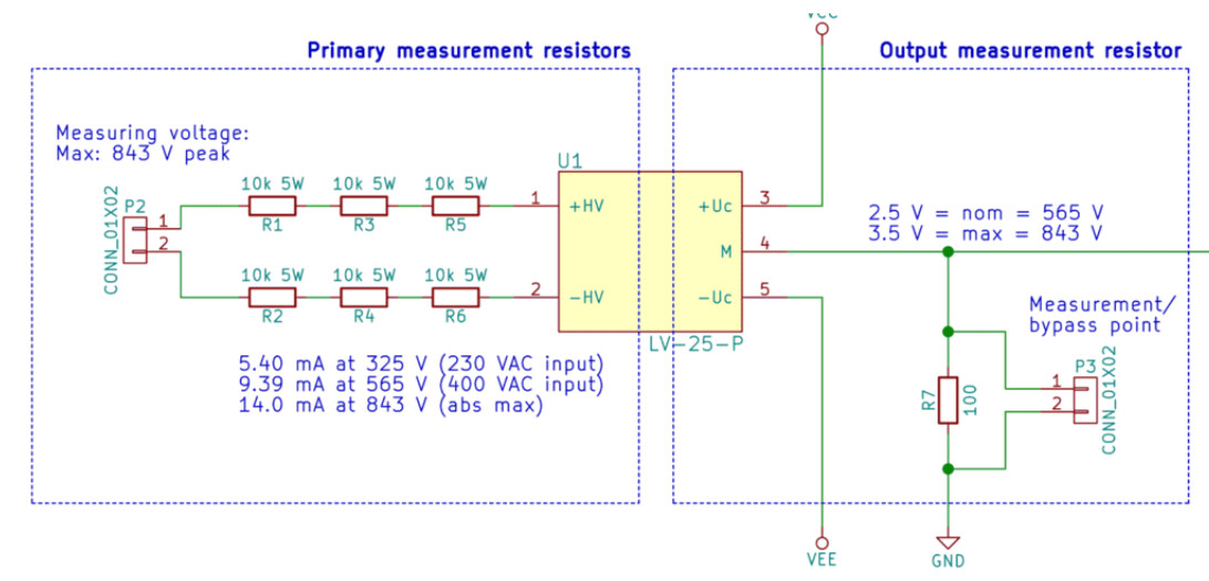
My research has yielded a LV-25P Voltage transducer. (data sheet and example schematic below).
I am eager to learn more about higher voltage sensing methods pertaining to battery bldc motor.
I assume a voltage dividing circuit can be utilized that is then fed into a galvanically isolated ADC-SPI bus? Or optoisoloator… but then I worried about response speed. My previous solutions appear overcomplicated or a bit expensive (digikey $88).
Thank you in advance for your input!
Whats wrong with a simple divider?
An ideal solution is often a simple one. A voltage divider is simple and checks that box.
I think about galvanic isolation as I experiment with higher voltages. Ground loops, unwanted currents, failed components giving unexpected results, safety and circuit resilience.
This component is one that I have been considering;
I figured I might ask before burning up dozens components while I experiment.
Looks fine, but you will need a galvanic isolated power and step down the output to 3.3v. The bandwidth also seems a little on the low side for a fast motor. The cost of the entire circuit will be meaningful only for a relatively high end motor/driver combo.
You may also want to experiment with linear optocouplers.
https://www.digikey.com/en/articles/linear-optical-isolation-for-safe-sensor-operation
Even this may be a little expensive, so I’ve done a project with a really simple cheap optocoupler (opto-isolator) where I calibrated the response curve myself and achieved a linearity of over 99% which for most cases is pretty good. Only needed a few resistors, the optoisolator and a couple of capacitors. Problem is that you need to do that inside the code yourself and it’s a little tricky if you haven’t done this before, involves a very careful experiment with least squares fits of second degree in a spreadsheet or something then put the coefficients in the code and run the calculation on the fly. Also each isolator is just a little bit different so you need to perform a secondary test to shift the curve a little up or down. I used Lite-On LTV-355T lscs part number C10803. The cost of the whole circuit was 20 cents.
Cheers,
Valentine
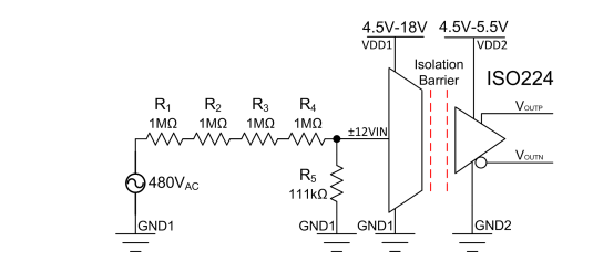
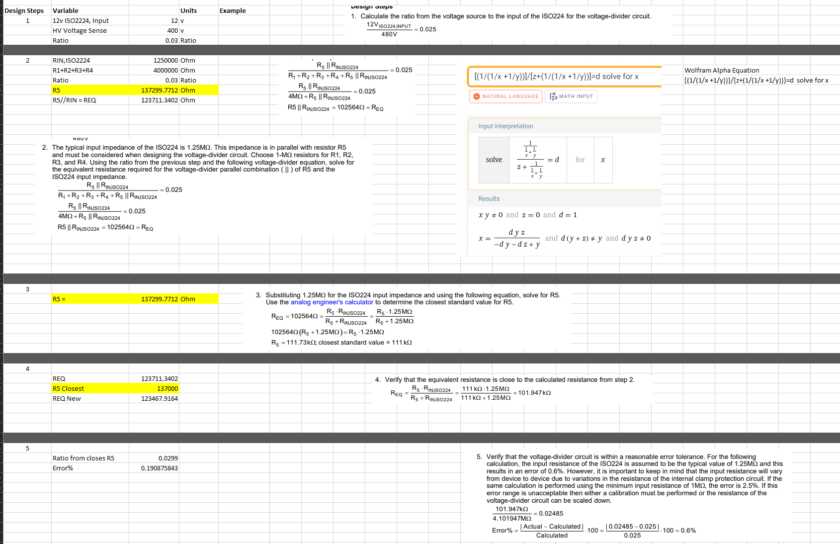
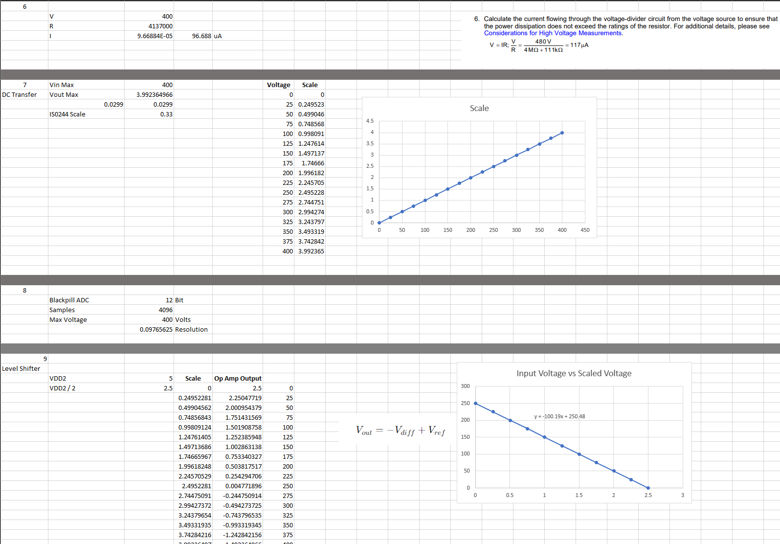
I do not know if this will help anyone, I did ultimately begin experimentation with the ISO224. As Valentine points out, this is not the cost-effective route, nor do I know if I will continue with it in the future. I wanted to post some of the steps that I took while testing the evaluation board.
The Eval board has 2 build in op amps that allow you to choose a method of combining the differential output of ISO224. The last graph is ultimately what is read into the uC.