I am new to SimpleFOC and I’m struggling to get a smooth rotation with a high-power 48V 23A BLDC hub motor. I am using a custom board based on the STM32F405 MCU.
The Problem:
The motor is not spinning as expected. It vibrates violently (like a jackhammer) even at low speed commands (like 1 rad/s). I’ve tried setting a very low voltage limit (around 1V), but the motor remains stationary. Increasing the voltage limit only increases the vibration. I attempted to tune the PID values for closed-loop speed control, but I believe I need to achieve smooth open loop or basic rotation before moving to advanced tuning.
Hardware & Configuration:
Motor: BLDC Hub Motor (Shaft)
Pole Pairs: 23
Phase Resistance: 0.140 ohm (Phase-to-Phase). I entered 0.07 ohm in the BLDCmotor constructor.
Power Supply: 48V
Sensors: Built-in Hall Sensors
Current Sensing: Low-side sensing with 0.0005 ohm shunt resistors.
Library: SimpleFOC v2.4
Has anyone encountered this “jackhammer” vibration with high pole-pair hub motors?
Any guidance on how to get this motor spinning smoothly would be greatly appreciated. Thanks!"
Sounds like one phase is disconnected or has wrong PWM pin configured. Try an even lower speed command. With 23pp, 1rad/s will give 3.66Hz vibration. If it’s slowed down enough, you should be able to see it gradually rotate forward and then jump back.
I conducted a standalone driver test using the example project and double-checked the PWM pins and driver outputs; everything is configured correctly.
I also performed a continuity test on the motor phases with a multimeter. It turns out that one phase occasionally fails the test. This inconsistency might be the root cause of the issue.
I’m sharing the code I used for the low-speed test. After uploading and running it, I set the values to L: 4 and T: 1. As expected, the motor changes its rotation direction on its own (it jumps back), which confirms the behavior you described.
Hmm, that’s different. A disconnected phase would rotate about 10 degrees (360/23pp=~15° per electrical revolution, 1/3 of which isn’t working) and then jump back, repeating that pattern. Yours is stuttering (most likely once per electrical revolution) but still managing to move forward several electrical revolutions. And reversing to do several electrical revolutions in the opposite direction doesn’t make any sense at all.
Try a different motor and see if it does the same thing.
It might be the dead time that is a bit too high.
Given that you have such a high supply voltage 48V and such low voltage limit 0.1V.
In SimpleFOC we use 12 bit PWM resolution by default 0-4096 so this already means that your voltage setting is very limited 4096/0.1*48 = 8.5, you’re setting the PWM values in the range [-8, +8] Which is very low.
In that case then, maybe the 5% dead-zone is just too much making for voltages applied which are not sinusoidal any more.
So you can try:
lower the dead-zone to under 1% this should work for most of the modern mosfets and gate drivers
increase the voltage limit to 1V for example. For a short test at least your motor seems more than capable of handling it
Thanks for the suggestions @Antun_Skuric . Here is an update on my tests,
I reduced the dead-zone to 1%, which significantly improved the behavior. I also tried with 0.005f, and the ‘back and forth’ jumping issue seems to have disappeared.
However, the vibration/stuttering persists under certain conditions:
I set the voltage_limit to 1V and slowly increased the target speed.
The motor spins, but once it hits a certain speed threshold, it starts stuttering and shaking violently again.
If I increase the voltage_limit (e.g., from 1V to 4V) via the Commander, the threshold where the shaking starts moves higher, and the intensity of the vibration decreases, but it doesn’t disappear completely.
But if I increase the voltage limit too much like 7V the power suplly fan’s starts to scream. I am guessing that drive consumes too much current. Also If I increase the target speed while increasing voltage limit like L to 7 and T to 6 motor drive uses less current.
Ok so the second behavior you’re describing is normal for open loop control actually.
You can read more in the docs about different torque and motion control strategies.
I suggest you to use estimated current mode, rather than voltage mode. You need to provide the library with the phase résistance and the KV rating of the motor.
Once you set the current limit, the library will automatically calculate the voltage_limit that will be proportional to the velocity. If you set the Paramus well you should be able to run the motor at almost full range of velocities.
But it will still be worse and less efficient than in closed loop control mode.
My custom motor driver has low-side current sensing (with 0.5mOhm shunts), and I want to implement it properly. Before enabling the full FOC current loop, I want to verify if the ADC readings are accurate.Is there a healthy way to test the current sensing and compare the values with a multimeter?
My Plan:I am thinking of printing the values to the Serial Monitor. How can I print out the current values?
Also should I run the motor in a specific test mode (like a static voltage on one phase) to get a stable DC current reading for comparison?
Since my shunts are very low (0.0005ohm), I am worried about the signal-to-noise ratio. What is the best way to calibrate the gain and offset in SimpleFOC to match my multimeter readings?
Any advice on a ‘sanity check’ procedure for current sensing would be very helpful.
There is an example code in the library for this sanity check.
You can find ti here:
Adapt it a bit to your sistem, but the code should work out of the box more or less.
Use teleplot.fr for visualizing signals. And you can use the commander to inverse the currents and so on, and add additional features if necessary.
If you have the closed loop control working you can also go quickly through the getting started section of the docs:
The getting started guide is more focused on the control than the measurement accuracy so it only helps to very that you have qualitatively good values in tyou d and s currents.
It is also worth noting that SimpleFOC does do auto alignement of the current sense and the motor, and it verifies that the currents are well measured before it starts the FOC loop. It is definitely bulletproof but if you want you can also just try the full foc code and see if it will work out of the box.
In most cases it will be ok.
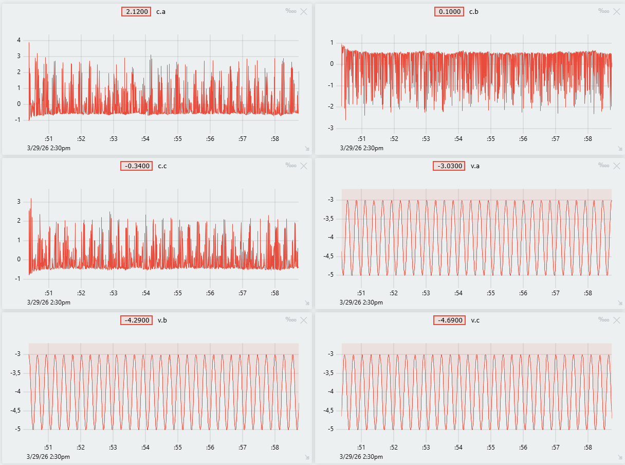
voltages ab and c aligned with currents a b and c. Basically that current has the same waveform as voltage a. The same for b and c. ( The magnitude is not important, only the waveform)
It looks like there is an issue with your current sensing. Are you using the low side current sense?
I think there is a problem on the current sense side. So I tried with estimated current control. As a result I can control the velocity of the motor better that open loop control. However motor can’t reach 650 rpm which is writing on the datasheet.
Why am I facing with this? For example although I velocity command is 20 rad/s, motor can not exceed the 17 rad/s.
Motor specs:
max velocity: 650 rpm
rated voltage: 48v
rated current 23A, 48A max
Motor specs link
The power supply specs that I am using is:
Meanwell 48V, 21A, RSP-1000-48
Also If I give the measured phase resistance (0.07) and motor KV (650rpm/48V) motor not moves. Vlues in the code snipped are empirical values which are can able the turn the motor.
Motor makes so much noise. What would be the cause?
So there are a couple of things that seem to be going on at the same time.
You’re testing your own board that might have some issues right? At the moment the current sensing is not really working well? But let’s assume that everything works except the current sensing.
The KV rating is set to NOT_SET in your code, this basically means that the code is not using it at all. Is that what you ended up using?
Did you try using the torque control mode only (I would suggest staying in this mode until you resolve your issues) and try to set the target current relatively high. The motor should accelerate to the max speed.
You can stay in the voltage mode too and set the target voltage at 24V.
If you cannot reach the max speed (or at least in the ball park, for example above 55 rad/s) there are a couple of options
hall sensors are generating too many interrrupts. Try using the HallSensor without interrups: Hall sensors | Arduino-FOC
If you’re in velocity mode the PID values are maybe not well set… Use the torque control mode until you can get to the desired velocity