Hello everyone,
I am new to SimpleFOC, and I’m struggling to get a smooth rotation with a commercial drone BLDC motor. I am using a custom board. Here are the main MOSFETs + MOSFET controllers schematic:
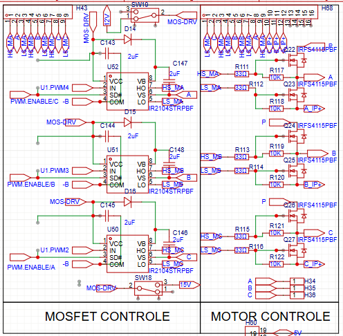
The Problem:
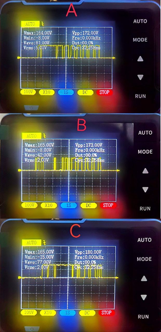
The motor is not spinning as expected. It vibrates violently (like a jackhammer) even at low-speed commands (like 1 rad/s). I’ve tried setting a very low voltage limit (around 1V), but the motor remains stationary. Increasing the voltage limit only increases the vibration. I need to achieve smooth open loop or basic rotation to make sure the base hardware works correctly before implementing the current sensing and the AS5600.
Testing steps:
First, I decided to use a normal commercial 1000KV A2212 Brushless DC Motor BLDC for the first test. Now, when I put T at (1-10) and increase L to (3-5), the motor starts moving/jerking back and forth. I also noticed that if I put my finger on the capacitors across the VCC/GND of the IR2104, the motor starts turning more than it jerks, but it still jerks nonetheless. And when I increase the L to 6, the power supply signals a short and stops supplying power.
Here is the code I am using:
#include <SimpleFOC.h>

BLDCMotor motor = BLDCMotor(7);

BLDCDriver6PWM driver = BLDCDriver6PWM(15, 2, 4, 16, 17, 5);

Commander command = Commander(Serial);

void doTarget(char* cmd) { command.scalar(&motor.target, cmd); }
void doLimit(char* cmd)  { command.scalar(&motor.voltage_limit, cmd); }

void setup() {
  Serial.begin(115200);
  SimpleFOCDebug::enable(&Serial);

  driver.pwm_frequency   = 20000;
  driver.voltage_power_supply = 15.5;
  driver.voltage_limit   = 12.0;
  driver.dead_zone       = 0.06f;

  if (!driver.init()) {
    Serial.println("Driver init failed!");
    return;
  }

  motor.linkDriver(&driver);
  motor.controller     = MotionControlType::velocity_openloop;
  motor.voltage_limit  = 0.5;

  if (!motor.init()) {
    Serial.println("Motor init failed!");
    return;
  }

  motor.target = 5.0;

  command.add('T', doTarget, "target velocity [rad/s]");
  command.add('L', doLimit,  "voltage limit [V]");

  Serial.println("✅ A2212 safe open-loop test ready");
  Serial.println("1. Set power supply current limit to 4-5A");
  Serial.println("2. Send L 0.5   then slowly increase");
  Serial.println("3. Max recommended for now: L 8");
}

void loop() {
  motor.loopFOC();
  motor.move();
  command.run();
}
I got it off of this post that was having a similar issue, but only on bigger motors:
https://community.simplefoc.com/t/vibrating-problem-with-48v-23a-bldc-motor/8047
Here is a link to a YouTube video showcasing the problem in question:
Hardware & Configuration:
-
Motor: A2212 1000KV BLDC motor
-
Pole Pairs: 7
-
Power Supply: 15.5V
-
Sensors: no sensors for the moment (Hall/current sensors and magnetic encoder in the future).
-
Library: SimpleFOC v2.4
Any guidance on how to get this motor spinning smoothly would be greatly appreciated. Thanks!"