I’m certainly no expert on motor construction, it’s a complex topic. But I’ll make an attempt:
The permanent magnets on the rotor determine the number of poles and pole-pairs.
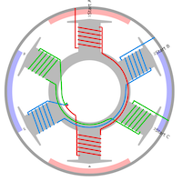
The coils on the stator are arranged in a geometry to match the rotor poles. The number of windings is always three, but the number of stator teeth these windings are wound onto varies along with the number of pole pairs. Certain geometries will work, while others (like you have drawn) would not work and get “stuck”.
You’ve drawn the motors with 2 respective 4 poles, but always 3 slots. The 4 pole motor would not be constructed with 3 slots, but probably rather 6.
Here is an excellent resource that explains it in depth, if you’re interested: Things in Motion: Selecting the best pole and slot combination for a BLDC (PMSM) motor with concentrated windings
The relevant part is this:
The slot to pole ratio with consideration for the number of phases is designated by the variable q. If q is less than 0.25 then the arc covered by a rotor pole is now less than half a stator tooth. This results in multiple north and south magnet poles interacting with each stator tooth and so the torque generated by the motor is reduced. Therefore, q values of less than 0.25 are generally not considered feasible and can be eliminated.
and:
Alternatively, if q is greater than 0.5 then it no longer makes sense to use a concentrated winding as a single rotor pole will span over multiple teeth. Instead, a distributed windings would be used.