Hmm, hot glue would have been my recommendation for the potentiometer wires if you hadn’t already tried it. Perhaps hot glue on the zip tie as well? The tie alone doesn’t prevent motion of the wires from reaching the solder joints, and hot glue alone might come loose, but the two together should hold the wires firmly against the solid structure so the segment between the tie and joint will hold still.
I think there are some STM32 models with 4 channels, but the 12 channel chip seems nicer to me since it would allow controlling all motors from a single MCU. You’d need to make a breakout board for it, but that’s easy enough to do by hand. Grind the bevel edge off an x-acto knife so it comes to a tiny chisel point and you can use it to carve traces. Either that or glue the body of the chip to a piece of wood or plastic and solder fine wires directly to the pins, and then glue the wires down as well for strain relief.
It sounds like your current code does pretty much the same thing, so probably not worth the trouble of getting it to work. But if you want to give it a shot, then I think the only custom code you’ll need is a potentiometer sensor class that calls analogRead in getSensorAngle and scales the value to radians (the STM32 implementation of analogRead is insanely slow, but one call per frame won’t kill you), and a driver class where setPwm sets the driver inputs according to the voltage sign and DAC output according to magnitude (though in this case the value would actually be in amps, not volts, which makes everything a little confusing).
Or if you’re sticking with PWMing the driver inputs, then probably the easiest way to go about it would be to use the BLDCDriver6PWM class. Implementing a complementary 2PWM would involve fiddling around in the hardware-specific code, which is the dark underbelly of SimpleFOC  I think you could use one 6PWM to control 3 motors, but it would involve a bit of hackery to get where you can call setPwm with the 3 motors’ voltages rather than having them individually call setPwm from within setPhaseVoltage. Perhaps have them talk to a dummy driver class that doesn’t do anything. The voltage.q that they pass to setPwm is cached in the base FOCMotor class, so you can still access it after they all finish their update. So the loop would look something like this:
for(int i = 0; i < 3; i++)
  motor[i].move();

driver.setPwm(motor[0].voltage.q, motor[1].voltage.q, motor[2].voltage.q);
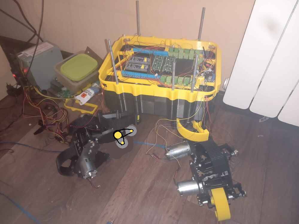
EDIT: Thanks, by the way! This is one of the reasons I enjoy forums. If not for hearing about and thinking about your wire breakage problem, I would have continued on my path to suffering the same fate. The 3D model of my robot had features to guide the wires along, but nothing that would firmly clamp them in place, so I’m sure my solder joints would have fatigued as well. Much easier to design in screw holes and structure for wire clips now before machining the parts than trying to shoehorn them in later. Hot glue might have been enough to save me, but motor wires may get hot enough to melt it.