Using BLDC motor for string based haptic force feedback

Hello community,
I am trying to create a haptic force feedback device with a bldc motor. On the motor is a thread which winds up a string by the rotary motion of the motor (see Image_1). By pulling the string I want to simulate constant forces. Unfortunately, i’m not getting a perfect constant force while pulling the string because I feel one jerk/cogging (caused by the poles?) every full revolution. Do you guys have any idea how I could manage to drive the motor with a constant force against its direction of rotation? Is this possible with a BLDC motor?

Motor: iPower Motor GM3506 (AS5048A Encoder)
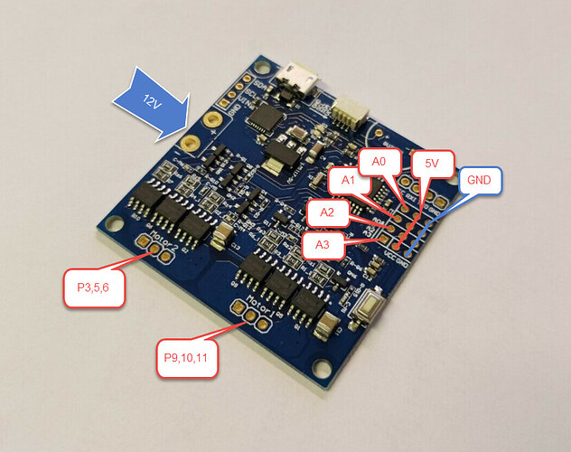
Board: Arduino Pro based BLDC Controller (Arduino Pro - based Brushless motor controller driver board (FOC BLDC servo). | eBay )

Image_1:

Code:

#include <SimpleFOC.h>
 
MagneticSensorPWM sensor = MagneticSensorPWM(A0, 4, 928);
 
// BLDC motor & driver instance
BLDCMotor motor = BLDCMotor(11);
BLDCDriver3PWM driver = BLDCDriver3PWM(9, 10, 11);
 
// voltage set point variable
float target_voltage = 2;

// instantiate the commander
Commander command = Commander(Serial);
void doTarget(char* cmd) { command.scalar(&target_voltage, cmd);}
 
void setup() {
 
  // initialise magnetic sensor hardware
  sensor.init();

  // link the motor to the sensor
  motor.linkSensor(&sensor);
 
  // power supply voltage
  driver.voltage_power_supply = 8;
  driver.init();
  motor.linkDriver(&driver);
 
  // aligning voltage
  motor.voltage_sensor_align = 5;

  // choose FOC modulation (optional)
  motor.foc_modulation = FOCModulationType::SpaceVectorPWM;

  // set motion control loop to be used
  motor.controller = MotionControlType::torque;
 
  // use monitoring with serial
  Serial.begin(115200);

  // comment out if not needed
  motor.useMonitoring(Serial);
 
  // initialize motor
  motor.init();

  // align sensor and start FOC
  motor.initFOC();
 
  // add target command T
  command.add('T', doTarget, "target voltage");
 
  Serial.println(F("Motor ready."));
  Serial.println(F("Set the target voltage using serial terminal:"));
  _delay(1000);
}
 
void loop() {
 
  motor.loopFOC();
 
  motor.move(target_voltage);
 
  command.run();
}

With this code I feel a jerk/cogging every full rotation… :confused:

Thank you for your help! :slight_smile:
Best, Fausto

Hey @Fausto,

It is probably due to the pwm sensor. They are the wors kind of sensors we support, and especially in combination with the atmega328 chip.

Did you try finding the min and max values of the sensor using the provided example sketch?

Can you hook up your sensor to the I2C?
Are the I2C pins available?

1 Like

Hey @Antun_Skuric,

thank you for your reply :slight_smile:

@Antun_Skuric
Did you try finding the min and max values of the sensor using the provided example sketch?

Yes, but without success…

@Antun_Skuric
Can you hook up your sensor to the I2C?
Are the I2C pins available?

i don’t think so. But i have seen that it is possible to connect a cable for SPI. Do you think it would be possible with that?

What does it mean without success?
What are the values you’ve found?

SPI is much better than I2C, and it will give you great results. :slight_smile:

1 Like

Hi @Antun_Skuric, the values shown in my example are the ones I found and which do not work as expected. :smiley: SPI sounds great but I guess that my board only supports I2C :roll_eyes:

Beside the marked pins on the picture there are also (SDA, SDL, VIN, GND); (VCC, RXI, TXO, GND) pins available. Do you have an idea if there is a way to connect the six cables for SPI with this board? If not can you recommend another one? Thank you very much for your help :face_with_head_bandage:
Best, Fausto.

AS5048A does not support I2C. You need AS5048B for that.

SPI on this board (atmega328p chip) requires PB2, PB3, PB4, PB5 (digital pins 10, 11, 12, 13), plus GND and VCC to supply the sensor.

Either I don’t see them exposed or they are already used internally. You may be out of luck.

You may want to contact the manufacturer for documentation. If lucky some of the non-marked pins may be the SPI ones.

One more thing, I don’t see any buffer capacitors, you may want to solder an electrolytic one where that round circly thingy with +/- sign is. Watch out for the correct polarity. Ask the manufacturer for a recommended size, else this board will be a bit jumpy. Your manufacturer cut a corner.

1 Like

Hey Valentine,
thank you very much for your time. I’ll check out your advice and keep you informed :slight_smile:
Best, Fausto