I’m not quite sure what type of current sensor i should use for inline current sensing. I’m probably going to use a hall current sensor from Melexis.
But I’m not sure if i need a bipolar current sensor or a unipolar sensor.
Of course with the unipolar sensor the resolution would be bigger.
The expected current in max 30A.
Bi polar I guess you mean current direction. You will need a bidirectional for inline. The current direction switches so you need one with sensing in both directions else you will end up with high side sensing only. Or low depending on the way you install it. If you want higher resolution you need a 5v one centered around 2.5v and use 5v adc however most mcus have 3.3v. the noise in the circuit will exceed the adc accuracy anyway. You will be fine with 3.3v bidirectional .
@Valentine what do you think would be better suited for the 30a igbt I’m using? 25A current sensor or 50A current sensor.
30A sensors from Melexis aren’t that common. That’s why I’m asking.
There is a fast 30A Allegro, please hold on. Let me check.
OK, the Allegro is not in stock.
MLX91221KDC-ABR-050-RE is probably your best choice. Bidirectional, fast, and simple to solder.
50A is better because you will always get overshoots. 25A will overload and max out very easily.
Make sure you get the SOIC-8 package.
Sensitivity is 25mV/A. Probably sufficient but rough if you need low current.
In other words you cannot measure anything under 1A.
The current sensors are more for Backup than anything, voltage control worked fine before. But if I’m doing a custom board I’m putting them on anyway.
Got any news on your igbt project?
And as always thanks for the help.
I submitted a ticket with On Semi, let’s see. Can’t get the PWM output, I may be making a mistake but can’t figure it out myself.
If you want lower current resolution definitely you need a shunt and op-amp.
I want to have the thing kinda universal and want to use it in the future at mains voltage, and the current shunt implementations I came across for high voltage always have many auxillary components, so i decided to go with the hall sensors.
As a alternative I can get acs712 30A PCBs for cheap locally i only need like 10 so I can desolder them, only problem is the thing is 5v output so i would have to use a voltage divider or something similar to get it down to 3.3v.
Agree, I like everything integrated, since I develop it myself and extra components are a lot of hassle to source. However, I saw new op-amps with integrated shunt resistors just came out, give me a sec, they are not yet available but will be in stock perhaps this year, a lot simpler.
INA254, 80V, High-Voltage, ± 50A Integrated Precision Shunt, Bidirectional, Zero-Drift Current-Shunt Monitor
Looks interesting but still only 80V.
So what would you do, MLX91221KDC-ABR-050-RE or acs712 30A with voltage divider?
My applications realistically only need 15-20a so easiest would be MLX91221KDC-ABR-020-RE and if i need bigger then i can swap in the 50a part.
I would like to control maybe something like a 3 phase asynchronous motor in the future. 230v ac or 400v ac rectified on a separate PCB and then in my igbt PCB so the igbt one is still universal.
At least Im trying to design the PCB and parts so it’s 600v DC safe.
You definitely need a current sensor. However at that voltage you probably want to go for a through-hole sensor. Bigger, but very fast and accurate. Hold on let me find one. I haven’t used through-hole in ages.
I am not touching high voltage, literally and figuratively. Don’t have the equipment and the need.
I mean the thing looks nice but its like 4 times the price of the MLX91221KDC-ABR-020-RE and the spec sheet of it says it has about 2kv isolation voltage. What problems would i encounter in your opinion?
That’s a cheap one that’s why the isolation is low, The through-hole sensors are faster and more accurate, that’s all. Yes, they are expensive.
No other advantage. You can stick to the SMT hall sensor.
Ok, thanks for the help, that was educational, all in all, I’m probably just sticking 3 MLX91221KDC-ABR-050-RE on there and see what I get.
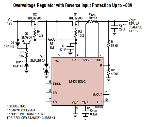
Also an other question, because you seem knowledgeable about that sort of thing, what’s your go to reverse polarity protection feature/circuit/part if you have one?
I’ll PM you with the schematics of the board I am working on. It’s only 10A at that point but will give you the correct idea. Later I will post it public however I have not tested it yet. Check your board mailbox.
Edit: Look the SMCJ24CA part (TVS Diode).
Edit2: For high voltage you will need a thyristor TVS. Please don’t electrocute yourself.
Edit3: Low voltage schematics
I will try not to electrocute myself /s, i know what to touch and what not👍, as the Russian guy said on yt: safety is our number one priority.
Anyway, thanks for the schematic, I’m going to look over it tomorrow.
I decided against using reverse polarity protection (lower parts count/BOM cost) and switched all my connectors from terminal blocks to xt60 and xt30, so the only critical thing is to get everything connected once the right way and the it should be alright. Only thing is XT 60 is a bit questionable with higher voltage but we will see.
