Hello there,
I finally received my new driver boards with current sensing hardware (it’s like fifth take ![]() ). While being super happy that the driver redesigned to use STM32 is finally working I found myself struggling with interpreting the “various currents” that I can get from the
). While being super happy that the driver redesigned to use STM32 is finally working I found myself struggling with interpreting the “various currents” that I can get from the LowsideCurrentSense class instance.
Just to provide some info about the hardware:
- DRV8302 based driver
- 2x 10mΩ shunt resistors in lowside current sense configuration
- op-amps used are built into the DRV chip
- sensing only phases A and B
- STM32F103CB MCU
- AS5048A magnetic encoder connected over SPI
I’ll try to divide the question into multiple sections to make it more readable:
(all the measurements provided were done in torque-voltage mode)
Part one: PSU current draw vs. getDCCurrent()
So these two are apparently not the same thing at all ![]() . When I measure the current going from my PSU to the driver board I get 80mA at 20V. This result is completely different from the one I get from calling
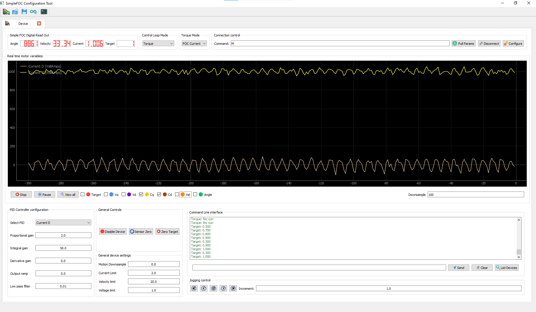
. When I measure the current going from my PSU to the driver board I get 80mA at 20V. This result is completely different from the one I get from calling getDCCurrent():
This is something that resembles a sine wave (with a lot of imagination
motor.voltage.q equal to 0.6V (the target of torque-voltage mode) the power output is more or less matching here (0.08A*20V=1.6W and 2A*0.6V=1.2W). Also the measurement from the PSU includes consumption of the MCU, CAN transciever etc.. so the difference is reasonable. This part comes down to: Am I right here? And what does the graph really mean? Is it a sum of all the phase currents?
Part two: Phase currents with/without load
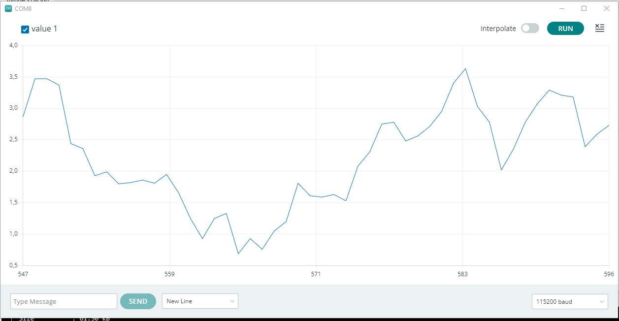
During further testing I stumbled upon a major difference between phase currents graph when the motor is and isn’t loaded.
Unloaded:
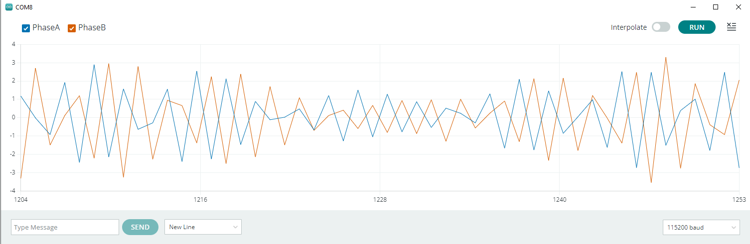
Loaded:
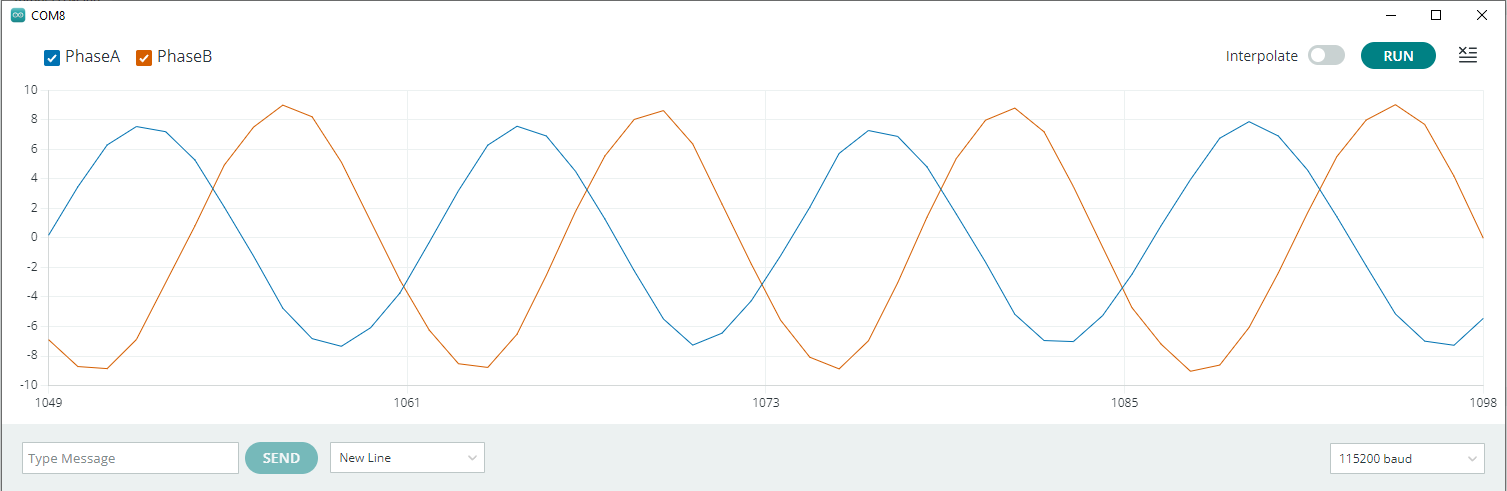
Is the first one just a property of the current sensing hardware? Is this difference normal?
Part three: Correct understanding of Id and Iq currents
If I get this one right the Id and Iq are obtained by measuring the phase currents and applying Park+Clark transformation (the Park guy also needs the rotor position). So essentially they’re just a representation of the “currently measured phase currents” in DQ coordinate space. Id and Iq are both numbers which when put together make up a vector that points in a direction of the magnetic field induced by the stator. And the goal is to move this vector so that it is always 90° ahead of rotor’s magnetic field vector thus creating maximum torque ![]() .
.
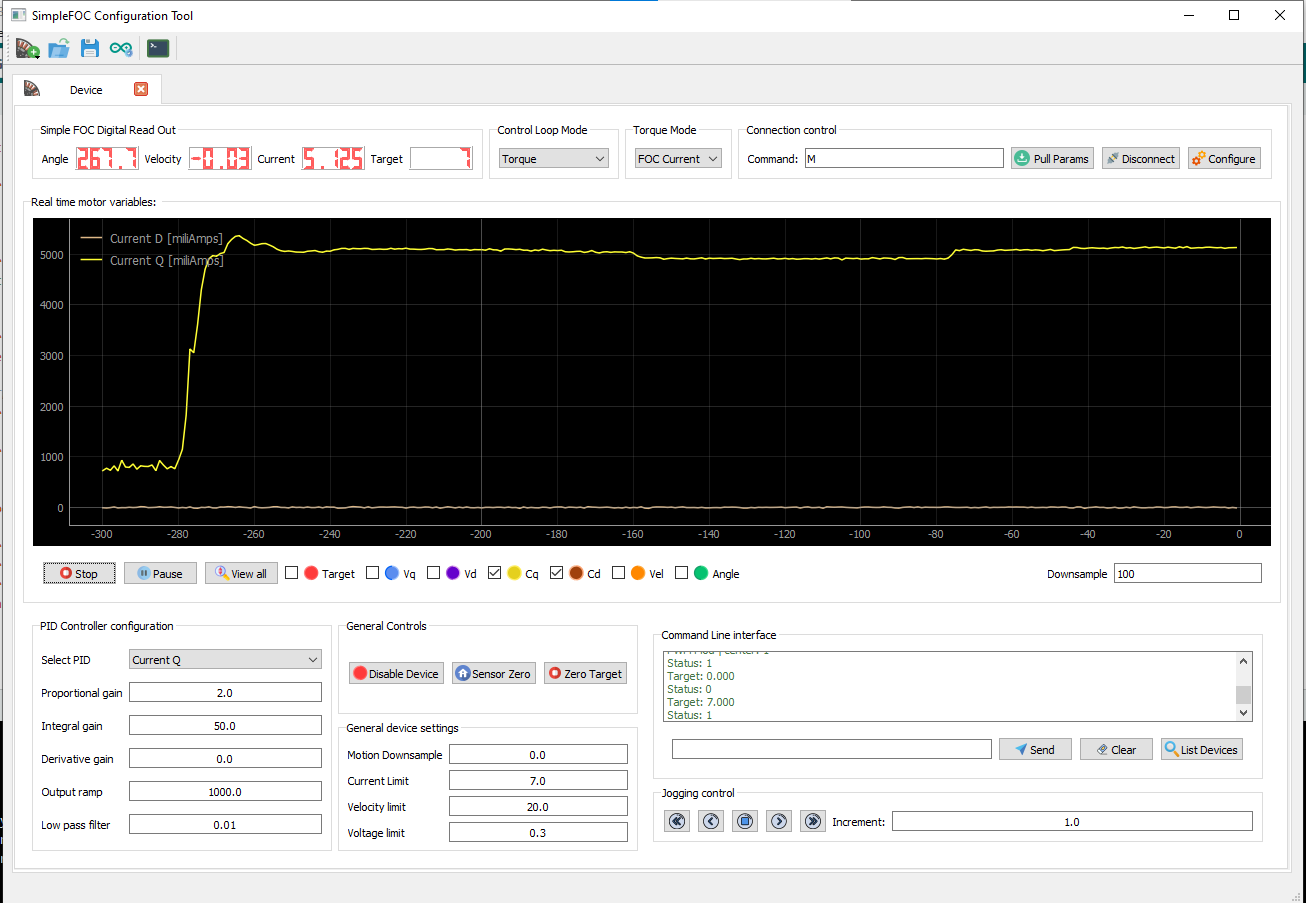
If I stop the rotor by hand (thus fixing the rotor’s magnetic field direction) I also fix the Id and Iq values since they have to be 90° from the fixed vector, right?
I feel like this screenshot supports it:
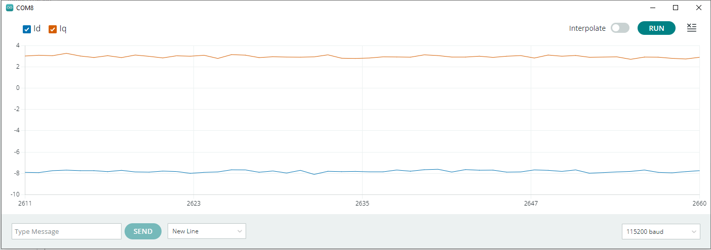
To make this part into a question again: Am I thinking about this correctly?
Part four: What am I getting with more advanced torque controllers
As of now, I am using TorqueControlType::voltage controller. The set-point here is voltage and my understanding is, that it is trying to mimic the behavior of regular DC motor. More voltage → more torque (but more RPM as well). And I cannot get rid of the dependency between RPM and torque, right?
If I move further to TorqueControlType::dc_current I get a behavior of a DC motor powered from constant current source, yes? But my physics intuition fails here. I would say that the motor will keep accelerating until the voltage generated by the motor (Back-EMF) is equal to the voltage created by the driver to sustain the constant current flow maybeeee?? Also the set-point with this mode is current Id and I’m really getting lost. How can I just set this? It will just mess up the vector of stator’s magnetic field and cause it not to be 90° ahead of the rotor’s one. I know I have to be extremely wrong here, but I can’t really figure it out based on reading documentation and watching youtube videos anymore ![]()
The ultimate goal is to separate torque and speed from what I understand. So I can spin the motor with constant speed but alter it’s torque which should be what TorqueControlType::foc_current is doing, right?
I know that this isn’t a standard format for forum question, but I hope someone will find time to go through it and clarify some of it.
Thanks,
Adam