Uncharacteristic problem - PWM high/low modulation on STM32G431KB nucleo possibly causing shoot through?

Hello everyone !
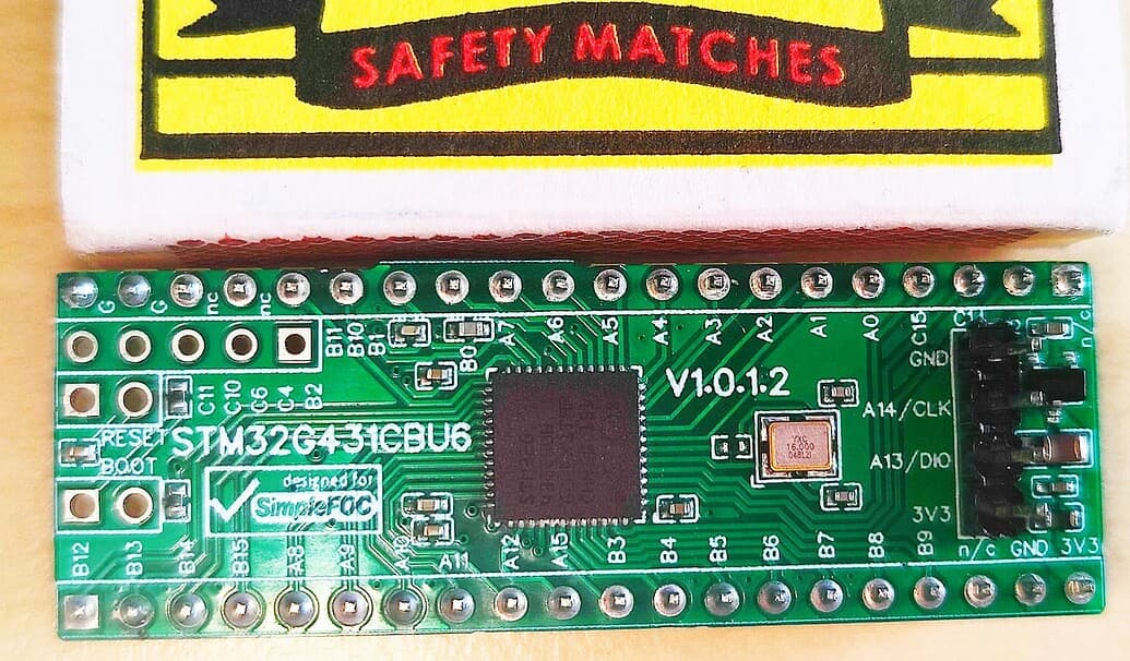
Im trying to build a basic bldc motor controller to work with simpleFOC. Its a simple circuit, and in the begining i was using IR2101 drivers. While testing the controller in open loop 6pwm, at first sight everything seemed to work fine. Some very minor stutters but the motor was rotating nicely, with good torque and speed. But after some more testing the drivers started to burn and were one by one stopping to work. I thought it was a problem with the circuit but couldnt find any. I decided to change the drivers to ir2103 with shoot through protection. To my big suprise after doing that the controller stopped working at all. No motor rotation and no current draw. But the nucleo is definetly sending signalas to the drivers, and the drivers definetly have the right Vcc. So of course the first conclusion was that there is a shoot through.

I had no other ideas left, so i decided to check the pwm signals that the STM is generaiting. I dont Have an osciloscope but i used a poor mans scope, made with an arduino.


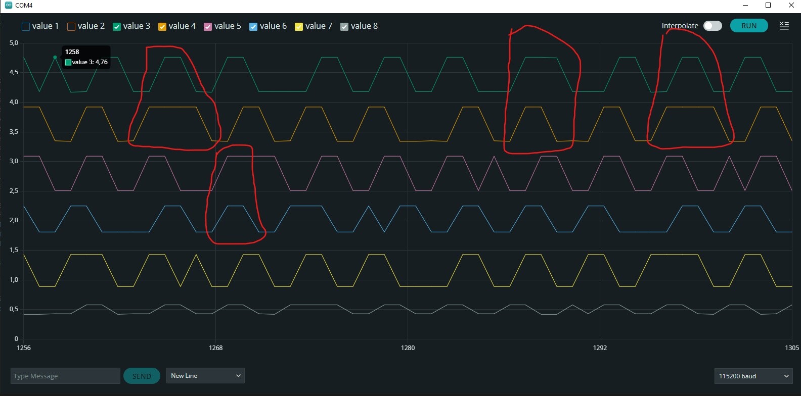
These are 2 random screens from the same test. The charts represent the voltages on each pwm pin starting from the top. So the top chart is Phase A High, the second chart from the top is Ph A Low, and so on.

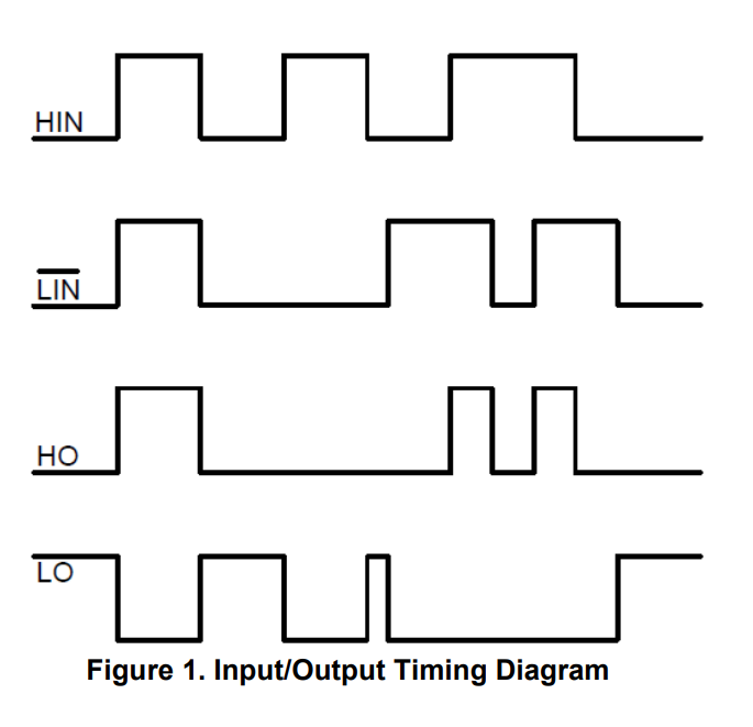
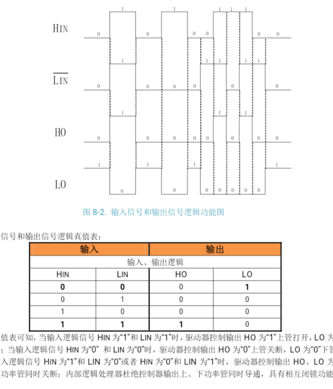
It’s not a perfect solllution but ther are visible moments when both, the High and Low pin, on the same halfbridge driver, are open at the same time. Can this be the reason there actually is a shoot through ?
Also
The voltages on the represented chart are not calibrated but i tested each one separetly, and they all equal 3.5V in high and 0.4V in low. With exception of the last chart becouse the Ph C low pin does not give out any signal for some reason.

I tested many different codes, changed parameters, reinstalled IDE and the libraries so i tried all the basic stuff. Might this be a problem with my pc config or the stm compatibility? It just looks like a very random problem ;/ .

Is anyone able to give me a hint what might be the thing causing this weird behavior? I searched through the forum and it seemed like nobody had a bug like that.

Gratefull for all the help!

@Lambert14

I have G431, if you post the exact code I can load it onto mine and test with a real oscilloscope, I assume this is open loop? Mine is CBU6 but the difference is just the pin count.

Valentine

@Valentine yes open loop. I added commander commands for testing but the situation was the same with just one static predefined speed.

// Open loop motor control example
#include <SimpleFOC.h>


// BLDC motor & driver instance
// BLDCMotor motor = BLDCMotor(pole pair number, phase resistance (optional) );
BLDCMotor motor = BLDCMotor(15);
//  BLDCDriver6PWM( int phA_h, int phA_l, int phB_h, int phB_l, int phC_h, int phC_l, int en)


BLDCDriver6PWM driver = BLDCDriver6PWM(PA8, PA7, PA10, PF0, PA9, PB0);


//BLDCDriver6PWM driver = BLDCDriver6PWM(6, 5, 11, 3, 10, 9);


//BLDCDriver6PWM driver = BLDCDriver6PWM(PA8, PA7, PA10, PB1, PA9, PB0);

// instantiate the commander
Commander command = Commander(Serial);
void onTarget(char* cmd) { command.target(&motor, cmd);}
void onMotor(char* cmd)  { command.motor(&motor,cmd); }

void setup() {


  Serial.begin(115200);
 // power supply voltage [V]
  driver.voltage_power_supply =14;
  driver.pwm_frequency = 1000;
 
 // driver config
  Serial.print("Driver init ");// init driver
  if (driver.init()) 
  Serial.println("success!");
  else{Serial.println("failed!");
  return;}
 
  // link the motor and the driver
  motor.linkDriver(&driver);

  // limiting motor movements
  //motor.phase_resistance = 0.5; // [Ohm]
  //motor.current_limit = 3;   // [Amps] - if phase resistance defined
  
  motor.voltage_limit = 5;  // [V] - if phase resistance not defined
  motor.velocity_limit = 50;  // [rad/s] cca 50rpm

  //driver.dead_zone = 0.02;
  
 
  // open loop control config
  motor.controller = MotionControlType::velocity_openloop;

  // init motor hardware
  motor.init();

  // add target command T
  command.add('T', onTarget, "target velocity");
  command.add('M',onMotor,"full motor config");
  
 command.motor(&motor,"E0");

   
  Serial.println("Motor ready!");
  Serial.println("Set target velocity [rad/s]");


  _delay(1000);

}
void loop() {
  
  // open loop velocity movement
  // using motor.voltage_limit and motor.velocity_limit
  motor.move();

  //motor.move(5);  
  

  // user communication
  command.run();
 

}

If you could check how it looks on your setup that would be great, becouse the more i look at the chart the more broken the modulation seems to be ;/.

Well I’ve got good news and bad news for you.

The code won’t work with the Serial the way you have done it, there is a conflict with the pins PWM selection for the motor timers. I commented all serial and commander calls and the PWM was perfect. So the G431 will work in your case, no deadband issues (I’m sure you just need a good oscilloscope) but you need to rewrite your code for different serial pins.

I only checked A7 and A8 pins, didn’t have time to check all three pairs, but usually if there is a problem with one they all go kookoo.

Good news: it works
Bad news: rewrite your serial and get a good two-channel oscilloscope. May be a logic analyzer would work too, since PWM’s are just like 1/0 logic signals anyways.

Even badder news: it may be your MCU is fried and does weird things.

Valentine

So the good news is your pin selection seems OK but your Serial needs to be rewritten.

This is the MCU I used in my test.

The exact code I used at the end:

// Open loop motor control example
#include <SimpleFOC.h>


// BLDC motor & driver instance
// BLDCMotor motor = BLDCMotor(pole pair number, phase resistance (optional) );
BLDCMotor motor = BLDCMotor(15);
//  BLDCDriver6PWM( int phA_h, int phA_l, int phB_h, int phB_l, int phC_h, int phC_l, int en)


BLDCDriver6PWM driver = BLDCDriver6PWM(PA8, PA7, PA10, PF0, PA9, PB0);


//BLDCDriver6PWM driver = BLDCDriver6PWM(6, 5, 11, 3, 10, 9);


//BLDCDriver6PWM driver = BLDCDriver6PWM(PA8, PA7, PA10, PB1, PA9, PB0);

// instantiate the commander
//Commander command = Commander(Serial);
//void onTarget(char* cmd) { command.target(&motor, cmd);}
//void onMotor(char* cmd)  { command.motor(&motor,cmd); }

void setup() {


  //Serial.begin(115200);
 // power supply voltage [V]
  driver.voltage_power_supply =14;
  driver.pwm_frequency = 1000;
 
 // driver config
  //Serial.print("Driver init ");// init driver
  if (driver.init()) 
  //Serial.println("success!");
  //else{Serial.println("failed!");
  //return;}
 
  // link the motor and the driver
  motor.linkDriver(&driver);

  // limiting motor movements
  //motor.phase_resistance = 0.5; // [Ohm]
  //motor.current_limit = 3;   // [Amps] - if phase resistance defined
  
  motor.voltage_limit = 5;  // [V] - if phase resistance not defined
  motor.velocity_limit = 50;  // [rad/s] cca 50rpm

  //driver.dead_zone = 0.02;
  
 
  // open loop control config
  motor.controller = MotionControlType::velocity_openloop;

  // init motor hardware
  motor.init();

  // add target command T
  //command.add('T', onTarget, "target velocity");
  //command.add('M',onMotor,"full motor config");
  
 //command.motor(&motor,"E0");

   
  //Serial.println("Motor ready!");
  //Serial.println("Set target velocity [rad/s]");


  _delay(1000);

}
void loop() {
  
  // open loop velocity movement
  // using motor.voltage_limit and motor.velocity_limit
  motor.move(0.01);

  //motor.move(5);  
  

  // user communication
  //command.run();
 

}
1 Like

@Valentine thank you very much for checking i will look into it more, hope the mcu is not fried.
So if i understand it correct, the code is going to work with commander commands, but i have to rewrite the serial? I think i dont exacly understand what that means.
If you could please explain, what do you mean with rewrite for different serial pins?

Please read up on STM32 Serial comms. The pins for the serial comms are mutiplexed with other pins and just calling Serial will default to whatever is in the .h files, and you need to reassign them to alternative pins so they don’t conflict with the PWM pins you selected. Default uart1 (PA9 TX, PA10 RX) are already assigned by you as PWM in your code so the whole thing pukes and the MCU hangs.

@Valentine Thank you very much once again! I read about it and you are obviously right. I will rewrite the serial.

Hey @Valentine
Im comming to you sadly only with more questions :frowning:
According to my previous posts

  1. As you said the mcu was actually fried, and it was the reason why one of the pwm pins, was not sending any signals. I bougth a new mcu - the same one, nucleo g431kb
  2. You were right, the serial com was connected to the pwm pins.

Now the problematic part
I hooked up the new mcu, and tested the program that you send me. Also tested other itterations of a very basic code, with no serial com and with one constant speed. However, it didnt make any difference. While using the ir2103 drivers, right after the program loads, there is a small tick from the motor (only sound). But as before, no current draw and no motor rotation.

I also bought new ir2101 drivers just to doublecheck. And again, the motor was rotaiting with minor stutters, but the drivers started to fry, and the mosfets were getting a little hot, even with very low current .

Furthermore, when i use an arduino nano, with the same basic code, the situation is the same for both driver types.

I didnt get the logic analyzer yet so i can’t show any decisive charts.

Do you have any tips on what can i try now? I am completely out of ideas. I am determinate to finish the project but i feel like a big dumdum.
I know i should get an osciloscope or logic analyzer and im planning to do it. Just dont have the budget for a proper one. Would a cheap chinese 24MHz logic analyzer be enough ?

1 Like

I need schematics, pcb layout and some hi rez pictures of the setup.

Probably. There are also some very low budget oscilloscopes you may want to explore, too, under $30, but some assembly required.

Yes, this is enough to monitor the PWM signals, which are only in the range 1-100kHz normally.
I use the cheap ones all the time for this, with the free PulseView application.

Ouch! For testing, which motor are you using, what’s the resistance? Have you set a driver.voltage_limit and motor.voltage_limit? When doing first tests, try to set these limits (and also the PSU itself) conservatively (i.e. low!) to help prevent things getting damaged.

Do you have pull-down resistors on your drivers’ and or MOSFET’s inputs? These can be important to keep the driver in a defined state when the MCU is starting up.

Are you working in ArduinoIDE or PlatformIO?

Normally, the G431 is well supported, and the PWM generation should work fine. Of course, dead-time could be too low at the default setting, you can try to increase it to see if this helps (driver.dead_zone = 0.1;).

@Valentine @runger i’m sorry for the delay, i ordered a logic analyzer to present some accurate charts.

The motor is a 250W, 36V, 15 pole pairs, electric scooter motor. I dont have a motor with less power so im trying to test carefully. The meassured phase resistance is around 0.6 - 0.7Ohms.

I have 10k pull-downs on HO and LO driver outputs to the MOSFET gates, and i am using ArduinoIDE

  1. The circuit schematics is basic, i wanted to add hall sensors for position feedback later. Right now i am powering the Nucleo from USB, for easier testing, but it is connected to common ground. The drivers also dont have a voltage regulator yet, so they are powered with the same voltage as the motor. That’s why im not testing above 20V. As for now, the schematics looks like that:

  1. With the logic analyzer I measured the PWM on the input of the drivers HIN, LIN.
    This is the chart of the signals, in HIN/LIN order, phase A is starting from the top.
    The program was basic, with no serial com. The test voltage was 18V.

My knowledge about PWM modulation schemes, is not the biggest, but in my opinion it looks correct. No shoot through caused by the PWM.

  1. I also analyzed the output signals from the drivers outputs HO, LO. Becouse if the inputs are ok, then there must be something wrong with the outputs themselves. The signals were meassured directly on the MOSFET gates. All the parameters were the same as before.


this is the whole view


this is more close up

Although I dont have enough knolwedge, these signals look very weird. For example, almost all of the High Side MOSFETs, are ON at the same time. And at the same time all of those High side MOSFETs are ON, all of the Low side MOSFETs are also ON.

  1. The setup:

I know it could be done much better and please excuse my solder work, it was already resoldered a few times. I tried to ensure everything is well isolated. There is sort of a power rail, made out of thicker wire. All the signal wires are isolated. There is a common ground point for drivers and mcu. There are 10mOhm power resistors for future current messuring, but looking like its going so far, i dont know if it will be possible to add that ;D. If i would be able to make it work, the next step was supposed to be, makeing an actual pcb out of it.

  1. In the end, i don’t understand why the output signals from the drivers look so broken. It looks like the problem is connected with the drivers but i don’t know what it is. I never managed to make the ESC work with the ir2103 drivers. Not even one turn of the motor.

Thanks for this extremely detailed and careful error report :slight_smile: that’s awesome.

The PWM does indeed look correct, IMHO.

This is normal. The PWM signals should all be centre-aligned if you’re using pins belonging to the same timer. So whatever on-time the phase has occurs with the same centre-point, and it’s normal the FETs are all open at the same time.

This is not normal, and it may not happen - otherwise you have created :“shoot-through” - a short circuit between VS and GND via the two FETs. Currents will go very high and things will burn.

Bit I think looking at the datasheet is clear why:

The low-side input of the IR2103 is labeled LIN with a bar on top, i.e. nLIN - this means the polarity of HIN and LIN is opposite, and LIN logic is active-low, i.e. a low input to LIN switches on the driver.
Ouch.

In the datasheet they describe this in words as:

  • High side output in phase with HIN input
  • Low side output out of phase with LIN input

What this means:
You need to drive the low side of this driver using active-low polarity. This is not the default option for SimpleFOC, but we recently added support for it on STM32 (which is what you’re using, lucky you :-D).

So to use it, you can:

  1. Use the dev branch of the library from GitHub. You can do this by replacing the library in your Documents/Arduino/libraries folder with a git clone from the dev branch.
  2. Add the option -DSIMPLEFOC_PWM_LOWSIDE_ACTIVE_HIGH=false to your build. In Arduino IDE it isn’t super-easy to add build flags, but you can find instructions on-line.

If you’re successful it will change the polarity as needed, and you should see that the high and low side FETs don’t open at the same time any more.

3 Likes

Thank you for help @runger, relieved to finally know what was the problem. A painful rookie mistake ;D.

I’ve read about what you told me to do and tried out a few options. But it didnt work as expected, so most probably i messed something up again.
So what i did was

  1. I cloned the SimpleFoc library dev branch from git hub to my pc with Git Bash
  2. Replaced the library files in the Documents/Arduino/libraries folder with the ones i cloned
  3. In the same folder as my global platform.txt file, i created a new file platform.local.txt
  4. I copied the contents from the platform.txt to platform.local.txt and used the property “compiler.cpp.extra_flags = -DSIMPLEFOC_PWM_LOWSIDE_ACTIVE_HIGH=false” to add the option in platfrom.local.txt
  5. Restarted Arduino IDE

In the end it didn’t work so i definetly messed up. The whole process seems a little unnecessarily complicated on ArduinoIDE. Is there a simpler, more reliable way of doing it? What if i would switch to PlatformIO? At first i was going to switch drivers, but the ones i would need, are a bit hard to get at the moment.

The way you describe your steps, it all actually sounds quite correct, so I am not sure why it would not work.
But as you say, working with ArduinoIDE is very complicated once you need things that aren’t built in…

Personally, I much prefer PlatformIO, but this is because I am used to complex IDEs and software development from my professional life. Other users find it overwhelming and confusing compared to Arduino IDE. Its a very personal choice, and hard to say what each person will find easier…

But in platformio these kind of things are much easier. The build flags can just go in your platformio.ini file, and the library can be git-cloned into the lib subfolder of your project… customization of the build process is more “built in” in platformio.

I wish I could say what the problem is in ArduinoIDE - what you did sounds correct, so its probably down to some detail… it should be possible to get it working in ArduinoIDE as well.

Sorry I can’t be of more help on this, and I do hope you find the issue soon!

Hi @runger , you think your suggestion from this post (Link) would work for this driver also? (using 3-PWM will enable pins?) The only thing is I don’t know if SimpleFOC will switch-On and switch-OFF the enable pins along with the HIN pins simultaneously?
Below is the timing diagram of the IR2103 for reference.

I used 3pwm mode with such drivers. Simply connected the output of each phase simultaneously to both driver inputs. A high signal opens the upper shoulder, a low lower one. I’m not an electrician, maybe it’s not right, but it works

1 Like

Hi @nikolaewich1988 , I think that’s the right way.
I’m trying to see if it’s possible to do the same through the MCU (supplying HIN and LIN*(_bar)) simultaneously through SimpleFOC (within the program).

No, it won’t, so this won’t work unfortunately.

This suggestion will work, I think. But check the currents carefully if you can. The driver has interlocking protection, but not dead-time insertion. So if I understand how it works correctly it really will switch both FETs at the same time. But FETs take some time to open or close, so in this case there can be a short time when both FETs are simultaneously open. It depends on the FETs, the drive voltage and other factors…
This would be the advantage of getting the 6-PWM working, because it will do dead-time insertion and thereby ensure that only one FET is open at the same time…

@runger Hello. I use eg2133 and used to think it had its dead time. Am I wrong?


My Chinese is not so good, but I would say yes, from picture 7-3…

But I meant @mizzi_labs , who is using IR2103, which I don’t think does it.