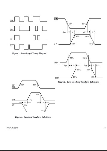
the ir2103 chart also has a dead time?
You’re right, and in this case the idea to use 3-PWM will work well!
great, thanks @runger, will try it out . Using 3-PWM instead of 6-PWM, the main draw-back is the control over dead-time is now relied upon the gate-driver only, right? Anything else, we may loose by using 3PWM instead? sorry for our beginner level questions. but truly appreciate all your efforts for this community.
That’s one drawback, but only an actual problem if the dead-time doesn’t suit your needs (FETs).
In your particular configuration with both inputs controlled from the same signal it actually also means you will always have one FET open, you can pick between high and low side, but one will be open (except briefly during dead-time). This means you can’t do things like switching all the FETs off for coasting or BEMF based commutation - but SimpleFOC doesn’t support these things yet.
Got it, thanks for the detailed explanation.
That was one thing I was worried about, if we’ll loose any performance by using 3PWM over 6PWM. Coasting and BEMF are not part of my scope yet. So, 3PWM works great!
Appreciate all the help.
For drivers which include enable, does simpleFOC allow you to use this for the hi-Z state in combination with the active high/low control pin? Control-wise it still comes out to needing 6 pins, but there are some drivers (like single half bridge gate driver) where this is required.
Edit: sorry, maybe that was too vague. I mean to use 3x of some chip like this, in place of a single-chip driver.
Yes, @VIPQualityPost , we support such drivers.
You can use 3 enable pins in the constructor to BLDCDriver3PWM, like this:
BLDCDriver3PWM(phaseApin, phaseBpin, phaseCpin, enableApin, enableBpin, enableCpin)
so you can have separate EN control for each phase. Then you can use 3-PWM but still have the option to close both FETs of each half-bridge via its EN signal.
In that case is there any difference between 3pwm and 6pwm other than the mcu is not in control of the dead time insertion? Well, it still has some control, but it doesn’t know about the additional insertion by the half bridge driver? I guess you can still configure dead-time in the software anyway so you can compensate.
Additionally, does this enable pin need (should?) to share the timer with PWM pin?
Hey, yes, but these are generally more “advanced” type motor control scenarios that we currently don’t yet support in the library. This would include things like:
- implementing plug braking vs. coasting
- implementing braking via external resistors
- implementing regenerative battery charging
- implementing other switching schemes, such as space-vector switching
no, any output capable digital IO pins can be used as a the enable pins. This makes 3-PWM “easier to use” than 6-PWM, where the pins should ideally all come from the same timer. It may turn out that not having the EN pins on the timer doesn’t work well for BEMF sensing though, once we get to implementing that… lets see ![]()
Many thanks to the people helping to figure things out. Man, things get so complicated so fast when you are trying to do something so basic. I think this kind of thing is a clear argument for a single, flagship, well supported board. Get all these details worked out so people can have something that they can stand upon. Let’s face it, how would anyone have figured this stuff out alone? Like the stuff with the serial comm requires such specific knowledge of one particular MCU architecture.
In keeping with the arduino philosophy of rapid prototyping and stuff, a single flagship board would really help. Mixing and matching gets real complicated real fast.

