Turntable vinyl with foc control: AS5048+rp2040+simpleFOCmini

Hello to all participants in this fantastic community,

I am trying to build a turntable; I have already built some with various motors, and now I am very curious to try one using FOC

To get started, I will use the following components:
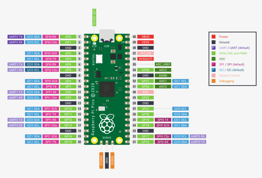
Raspberry Pi Pico, RP2040
SimpleFOC Mini
motor Gimbal Brushless GM3506
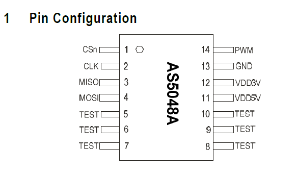
sensor AS5048

I have already seen that there is a very similar discussion to what I want to do:

Is Simple FOC an alternative to BGMC2 from RoverTec

And I have already tried to learn from its mistakes and discoveries to get started, such as using the rp2040 and the need for a closed-loop control.

I’m not very experienced in programming, so I’m trying to take it step by step by starting to test the AS5048 sensor. Below are the data provided by the seller:


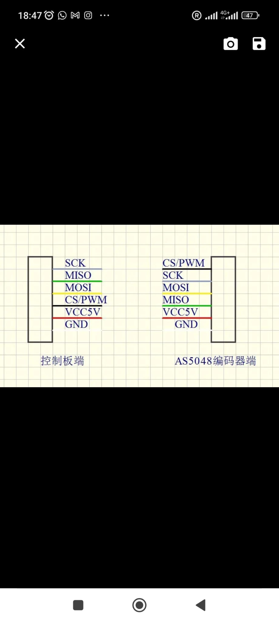
Image on the right: Pinout on the board side.
Image on the left: Pinout on the connector side.

As suggested, I am using the example sketch provided by the SimpleFOC library:
Magnetic_Sensor_Spi_example
And this is the code I am using.

#include <SimpleFOC.h>

// MagneticSensorSPI(MagneticSensorSPIConfig_s config, int cs)
//  config  - SPI config
//  cs      - SPI chip select pin 
// magnetic sensor instance - SPI
MagneticSensorSPI sensor = MagneticSensorSPI(AS5048_SPI, 17);
// alternative constructor (chipselsect, bit_resolution, angle_read_register, )
// MagneticSensorSPI sensor = MagneticSensorSPI(10, 14, 0x3FFF);

void setup() {
  // monitoring port
  Serial.begin(115200);

  // initialise magnetic sensor hardware
  sensor.init();

  Serial.println("Sensor ready");
  _delay(1000);
}

void loop() {
  // iterative function updating the sensor internal variables
  // it is usually called in motor.loopFOC()
  // this function reads the sensor hardware and 
  // has to be called before getAngle nad getVelocity
  sensor.update();
  // display the angle and the angular velocity to the terminal
  Serial.print(sensor.getAngle());
  Serial.print("\t");
  Serial.println(sensor.getVelocity());
}

I connected the CS pin, the black wire, to pin 17 of the rp2040, powered the sensor with 5V using an external power supply, and connected the rp2040 to pc

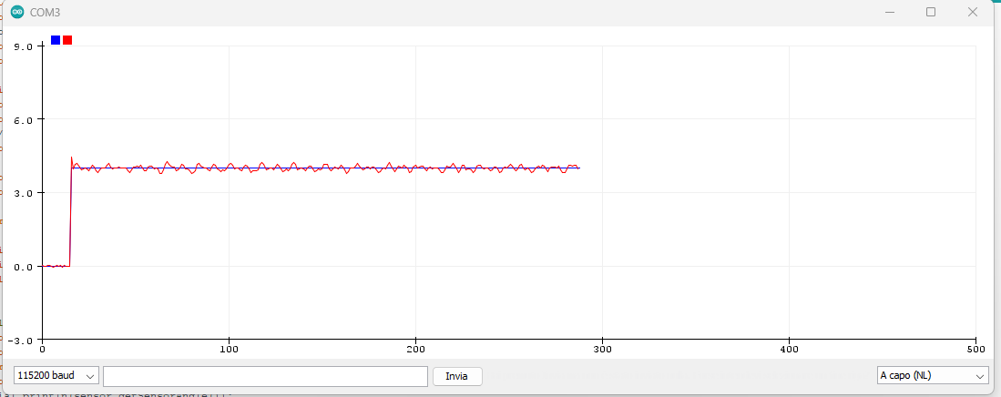
The code uploads successfully, but the serial monitor and plotter only display values of 0.00.

The magnet is integrated with the motor and sensor, so I’m quite sure it is correctly polarized for the sensor.

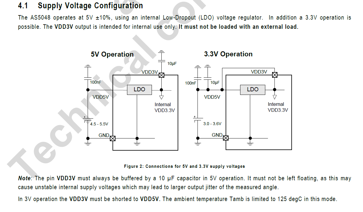
I have also read about issues regarding the sensor’s power supply, but the data provided by the seller only mentions 5V.

Where could I be making a mistake?
Another doubt I have is regarding the last code kindly shared by a user in the discussion link above, where three parameters of the SPI communication are defined:

// sensor data
const int clk = 18;
const int miso = 16;
const int nCS = 17;

Why am I only able to define the CS ?

Thanks to everyone for the help.

Hi @andrew1 , and welcome to SimpleFOC :slight_smile:

Very cool project! We’ve in fact had at least one SimpleFOC turntable recently, you should be able to find it in this forum…

So far so good!

Yes, the sensor is wired for either 3.3V or 5V supply, so you have to use the right one. Some boards have a solder jumper you can close or open to switch between them.

You code as is is using the standard pre-defined “SPI” object, with the standard default pins for SPI on RP2040. As long as you also used those pins to connect your SPI wires, this is fine and you don’t have to do anything.
If you used another set of SPI pins than the default ones, then there are ways you can change the pins or create a new SPI object. But its easier if you don’t have to.

I’m guessing the problem is either:

  • you’re using pins other than the expected ones. Solution: change wiring so as to use the default Pico SPI pins.
  • when the sensor is in 5V mode, it also expects 5V logic. the 3.3V output of the Pico is not sufficient to properly speak to the sensor in 5V mode. Solution: use a different 3.3V sensor, switch the sensor you have into 3.3V mode (if that’s possible) or use a “level shifter” between the 5V sensor and the MCU.

Another Note:

While the RP2040 is no doubt the better MCU for motor control, if you have an old Arduino UNO or Nano lying around, those are 5V MCUs and you could quickly test the sensor using those… but ultimately you’d want it working on the much faster 32bit Pico, so not sure its worth it.

1 Like

Hi @runger , Thank you very much for the response, always very clear and comprehensive. You’ve already helped me a lot indirectly on other topics, hahaha.

I figured, by “different set” do you mean, for example, the example sketches in the magnetic_sensor_SPI_alternative_example? But now I have another doubt, hahaha, why would it be necessary? I don’t think it’s necessary to use a different set than the default one in my application, am I wrong?

I read that the default CS pin for the Pico is GPIO17 (22), and I reloaded the sketch since I wasn’t sure to rule out this issue. I also tested all the other CS pins, but still got a reading of 0.00.

I hope at this point the issue gets resolved by using the correct power supply voltage. Thanks for the advice; in the meantime, I’ll use the fastest method to ensure the sensor is working and proceed with the next step.

Yes, although which pins can be used, and even the exact mechanism of initialising the SPI object differs slightly from MCU to MCU…

So for the Pico, the pinout diagrams typically show this:

So the dark pink pins (right hand side) are the default SPI pins. Arduino framework makes these available using the standard SPI object.
But you could initialise SPI also on any of the pin-sets in lighter pink on the left-hand side. It also shows that no matter which pins you use, there are a maximum of 2 SPI channels you can use on the Pico: SPI0 and SPI1. And SPI1 has significantly fewer choices for the pins available…

No, I don’t see a good reason. On other MCUs, sometimes the default SPI pins are needed for the PWM configuration, so then you choose other SPI pins. Or some poeple are running 2 motors, so they need 2 sensors and therefore another SPI channel… but if you don’t need these special cases, then better to stick to the default. All the examples will apply directly, and things will be much easier.

Note that for the nCS pin it does not matter, the nCS pin is the exception. You can use any output capable pin, it does not have to be the default one.

1 Like

Thank you for the clarifications.

I have connected all the pins correctly to the default SPI pins of the RP2040. I also noticed that the pinout provided by the seller was incorrect, so I rechecked the entire pinout with a tester. Now, I believe I can discard this issue.

I assume that my board is set only for 5V. I could try modifying the board configuration as shown in the third image “3.3 operation”, and at that point, everything should work."

Immagine 2024-01-19 171633

Cattura

thx <3

1 Like

Hello everyone,

In the end, I decided to change the sensor board and bought this AS5048,
powered at 3.3V and connected all the default SPI pins. However, the sensor still returned values of 0.00. I noticed though, that by leaving the example test name as5047 instead of using the name of my sensor (in the code line below), the code works:

MagneticSensorSPI sensor = MagneticSensorSPI(AS5047_SPI, 17);

Could you confirm this for me? Do you think it’s possible?

Also, I would like to ask for some clarification on the motor I’m using: the Brushless Gimbal Motor GM3506.

Are there any speed/torque graphs available? The nominal speed of the motor is approximately 1500 rpm. For my turntable, I want to test both direct drive and belt-driven operation, but I can’t find information on how torque varies with speed, and how closed-loop FOC control affects speed and torque. Does this type of control allow the motor to operate at extremely low speeds? And how does the torque behave? Could someone clarify these aspects for me?

Thanks again to everyone, and have a great day.

Yes, that should be ok because these sensors are protocol and register compatible enough that the generic angle readings will work.

You may do better using the dedicated AS5048A driver from our drivers library, which will also let you access the other registers.

Not that I’m aware of, but if you find some let us know. :slight_smile:

Using SimpleFOC you can use closed loop control to control torque and speed independently.

Of course there is a certain correlation in that you need certain torque levels (currents) to reach certain speeds, but assuming you’re operating within the limits you can control the motor speed while also controlling the maximum torque it will manifest. SinpleFOC will keep the actual current used to that needed for the speed and load.

Generally speaking yes. You’ll need to choose the right kind of motor, and performance will be influenced by the “motor cogging”. You’ll have to tune the system, but once you’ve achieved that then very low speeds should be possible.