Torque control FOC current

Hello my friend how to set PID parameters in torque control using foc current for MCU STM32 Nucleo F401RE. And in the example there are only arduino uno/mega parameters

Yesterday, if I tried with default, the motor ran unstable.

Please help friends and their directions so that my motor can rotate stably with a current sensor

Hi @Ganang_Aji ,

Unfortunately no one can tell you the correct parameters to use, they are individual to each setup.

Typically, PID values are determined empirically, i.e. by trying it out.

Set up your system in a way so that you can use Commander or SimpleFOC Studio to tune the PID values while the motor is running.

Then start with the values from the example, and tune them until you find values that work for you.

I have some simple hints for how to make this procedure likely to work:

To tune the PID values there are different methods, including formal math-based ones that you could look up on the internet or in the literature and follow. But here is a simple “ad hoc recipe” that works in many cases:

First question to look at: is the closed loop torque-voltage mode working well? That needs the sensor, but not the PID tuning. So if this mode is working as expected, it means the sensor and sensor alignment are working, and the basic motor parameters (like pole count!) are correct. Then try closed loop velocity. For this you tune the velocity PID. One method can be:

  • in closed loop torque-voltage mode, set up some output in a way that doesn’t affect motor performance but allows you to track the actual and target velocity (e.g. use the Arduino Serial plotter or just plain serial output. You can see the section on monitoring in our docs for one way to log this data)
  • Once logging is working to your satisfaction, switch to velocity mode
  • set P,I,D to 0, and slowly raise P, in small steps of 0.05 or 0.1 until you get oscillations, e.g. until the velocity oscillates near to or around the target value. Then take it back until there are no oscillations.
  • then raise I in small steps until the velocity tracks the target value well.
  • D can usually be left at 0
  • try different speeds and maybe loads on the motor, and see if the behaviour is good. If closed loop velocity is working well, closed loop position usually works well too, without much difficulty. Start with an angle P value between 1 and 20, and see how that behaves, try some lower or higher values until you get a good tracking of the position without too much “jitter” when settling into position.
1 Like

Thanks for the answer, but I still have a few questions

For closed-loop torque experiments, but not in the voltage mode, the motor can run.

but sometimes PP checks fail sometimes PP checks Ok, I don’t know what caused it so that the PP readings sometimes go wrong.

Question

  1. Sorry, first of all, I’ve never tried speed control. Does the sequence after torque control have to go to speed control first?

  2. So the P, I, D settings can be like using this?

// instantiate the commander
Commander command = Commander(Serial);
void doMotor(char* cmd) { command. motor(&motor, cmd); }

// add target command M
command. add(‘M’, doMotor, “motor”);

  1. Setting LPF_current is the same as looking for P,I,D values?

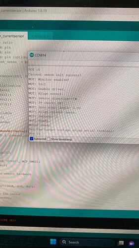
Maybe this is an example of the closed loop torque control experiment that I did, this can change speed according to the command. add ‘T’ 1 to ‘T’ 10 the motor will change speed and sometimes the PP check fails like the photo I linked.

Regarding the PP check, there can be many reasons for the PP check failing. If it is succeeding most of the time, and only sometimes failing, then this is already good because it means the sensor is working in principle.
Things you can check:

  • if using a magnetic sensor, check the magnet is the correct diametrically magnetised type, and check the magnet is properly and securely mounted and can’t move.
  • you can try to set the motor.voltage_sensor_align parameter to a lower limit.
  • if the motor is loaded or has friction, remove the load/friction for calibration.
  • check your sensor connections: is the cable secure and not subject to contact failures?
  • how long are the sensor cables? Maybe they are too long?
  • do you have all required pull-up resistors if using encoders, hall-sensors or I2C? Maybe the pull-up values are too low/too high?

These are some ideas to check into.

Note that if the PP check fails, you should not try the PID tuning. You should only tune PID on a run where PP check succeeds.

Ah, I see also now from the other thread that your motor only has 2PP… this will be difficult to tune. With such low PP the motor will move a lot to find the zero position, and will be subject to oscillations.

You can try to set the voltage limit for sensor alignment to see if it helps.

Yes, that’s right, yesterday I tried to control the torque in current foc mode with no PID, you could say everything was “0”, but when it was on, the motor immediately rocked irregularly and when I opened the throttle, it could spin, but it was really rough and only reached T “1” then I try to add a throotle to T “2” and the motor will add irregularly it’s a voltage condition of 20 and 1 ampere

here I use a hall sensor of course I have given a 10k pull up resistor

Hi @runger

this is a video when I use torque control using current foc mode

before open throttle the motor is vibrating

Hard to say what’s going on from the Video, but you should not directly try foc_current mode. First open loop control and closed loop torque-voltage mode should be working well, if at low voltages. This means that sensor and PP check have to work reliably.

Then you can try other modes like velocity or current control which depend on the lower level modes working well.

But if this motor really has only 2PP, and you’re using hall sensors, then I think it could be very difficult or even impossible to get it working.

What’s the winding resistance of this motor?

1 Like

@runger

as far as I know the PP is 22 and the phase resistance is 1.2 ohms

maybe next what do you think I do first?

I think my open loop is good, because the high side and low side are good

is it possible for me to try close loop torque
next close loop torque mode voltage
next speed control
next close loop dc current mode

or maybe i try the closed loop dc current mode because the closed loop torque is smooth

this is a photo of the motor earlier

@runger

sorry do you want to correct my program for control torque whitout foc_current?

#include <SimpleFOC.h>

// BLDC motor & driver instance
BLDCMotor motor = BLDCMotor(22, 1.2);

// BLDCDriver6PWM driver = BLDCDriver6PWM(pwm HIGH , pwm LOW , pwmHIGH , pwm LOW , pwm HIGH , pwm LOW );

BLDCDriver6PWM driver = BLDCDriver6PWM(PA8 , PB13 , PA9 , PB14 , PA10 , PB15 );

// InlineCurrentSensor constructor
// - mVpA - mV per Amp ratio
// - phA - A phase adc pin
// - phB - B phase adc pin
// - phC - C phase adc pin (optional)
//InlineCurrentSense current_sense = //InlineCurrentSense(40.0, PB0 , PC1 , PC0 );

// hall sensor instance
HallSensor sensor = HallSensor(PB3, PB4, PB5, 22);

// Interrupt routine intialisation
// channel A and B callbacks
void doA(){sensor.handleA();}
void doB(){sensor.handleB();}
void doC(){sensor.handleC();}

// voltage set point variable
float target_voltage = 0;

// instantiate the commander
Commander command = Commander(Serial);
void doTarget (char* cmd){ command.scalar (&target_voltage, cmd); }

void setup() {

// initialize encoder sensor hardware
sensor.init();

sensor.enableInterrupts(doA, doB, doC);

// link the motor to the sensor
motor.linkSensor(&sensor);

// driver config
// power supply voltage [V]
driver.voltage_power_supply = 65;
driver.init();

// link the driver to the current sense
//current_sense.linkDriver(&driver);

// link driver
motor.linkDriver(&driver);

// aligning voltage
motor.voltage_sensor_align = 3;

// init current sense
//current_sense.init();

// init current sense
//if (current_sense.init()) Serial.println(“Current sense init success!”);

//else{
// Serial.println(“Current sense init failed!”);
// return;
}

// link motor and current sense
// motor.linkCurrentSense(&current_sense);

// choose FOC modulation (optional)
motor.foc_modulation = FOCModulationType::SpaceVectorPWM;

// set torque mode:
//motor.torque_controller
//TorqueControlType::foc_current;

// set motion control loop to be used
motor.controller = MotionControlType::torque;

// foc current control parameters (Arduino UNO/Mega)
//motor.PID_current_q.P = 5;
//motor.PID_current_q.I= 1000;
//motor.PID_current_d.P= 5;
//motor.PID_current_d.I = 1000;
//motor.LPF_current_q.Tf = 0.005;
//motor.LPF_current_d.Tf = 0.005;

// use monitoring with serial
Serial.begin(115200);

// comment out if not needed
motor.useMonitoring(Serial);

// initialize motor
motor.init();

// align sensor and start FOC
motor.initFOC();

// add target command T
command.add(‘T’, doTarget, “target voltage”);

Serial.println(F(“Motor ready.”));
Serial.println(F(“Set the target voltage using serial terminal:”));
_delay(1000);

}

void loop() {

motor.loopFOC();

motor.move(target_voltage);

command.run();
}
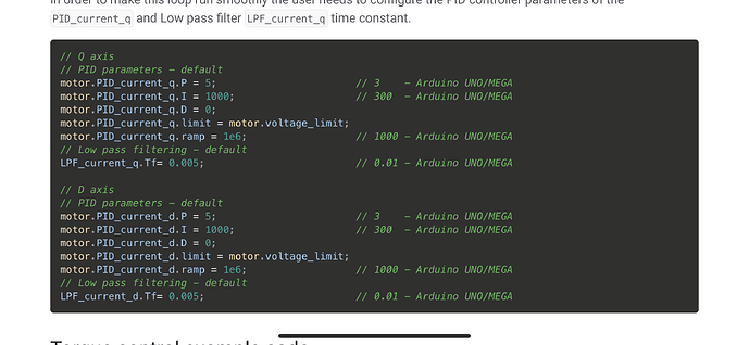
there is an error there, but that would have been revealed soon enough.

I noticed the example at FOC Current Mode | Arduino-FOC (simplefoc.com)
Does not have the resistance of the motor. I think that might mess things up. When you give it a resistance the behaviour of the torque mode changes and that might be messing up that layer.

Also I don’t think you can comment out the pid parameters, there must be defaults but that could be your problem and you will need to adjust them. I would just try to weave together the code you posted with the example code above, make it as close to the example as you can with the pole pairs etc. that are specific to you. Then take it from there.

I was never clear what units the PID gain parameters were in. I would make them in amps per radian of error or something. This seems to be acommon issue in PID controllers, they use arbitrary units, but that makes it hard to know how to start when tuning them.

1 Like

@runger

program code like this or what if it’s wrong, please correct it.

here is the code to set the PID

void setup() {
// instantiate the commander
Commander command = Commander(Serial);
void doProportional (char* cmd){ command.scalar (&target_Propotional, cmd); }

// add target command T
command.add( 'P’, doProportional, “target Proportional”);

motor.PID_current_q.P (target_Propotional);

}