Hi,
I am planning to use XESC with Simple FOC firmware.
I tested hardware with XESC test firmware and it works ok.MCU can communicate with TMC6200 and i also tested it with VESC firmware for it.
The issue i am having is i cannot communicate with TMC via Simple FOC firmware and can’t use it.
I am a newbie for Simple FOC and SPI protocol, read a lot of documents regarding this. Here is my platformio file:
[env:genericSTM32F405RG]
platform = ststm32
board = genericSTM32F405RG
framework = arduino
lib_deps =
	askuric/Simple FOC@^2.3.1
	simplefoc/SimpleFOCDrivers@^1.0.5
monitor_speed = 115200
monitor_port= COM3
lib_archive = false
upload_protocol = stlink
build_flags =
	-DSERIAL_UART_INSTANCE=1
    -DPIN_SERIAL_RX=PB11
    -DPIN_SERIAL_TX=PB10
    -D HSE_VALUE=8000000U
And here is my main.cpp file:
#include "Arduino.h"
#include <SimpleFOC.h>
#include "SimpleFOCDrivers.h"
#include "drivers/tmc6200/TMC6200.hpp"
InlineCurrentSense current_sense = InlineCurrentSense(0.005, 20, PC2, PC1, PC0);
TMC6200Driver6PWM driver = TMC6200Driver6PWM(PA10, PB15, PA9, PB14, PA8, PB13, PC9, PB5);
BLDCMotor motor = BLDCMotor(8); //FOR HDD MOTOR
Commander command = Commander(Serial); //OK
void doTarget(char* cmd) { command.scalar(&motor.target, cmd); } //OK
void doLimitCurrent(char* cmd) { command.scalar(&motor.current_limit, cmd); }
int faultIn = PB7; // FAULT OUTPUT OF DRIVER CONNECTED TO PIN PB7 //OK
int ledPin = PB0; // LED CONNECTED TO DIGITAL PIN PB0 //OK
int faultState = 0; // VARIABLE TO STORE THE DRIVER FAULT STATE //OK
int drive_en = PB5; //TMC6200 DRIVE ENABLE PIN PB5. IT IS USED WHILE SETTING UP WHILE 6PWM DRIVE MODE AND CYCLING IF SOME FAULT IS DETECTED.
/* SPI1 pin defs */
#define P_MISO PB3 //OK
#define P_MOSI PB4 //OK
#define P_SCK PC10 //OK
#define P_SSEL PC9 //OK
SPIClass SPI_1(P_MOSI, P_MISO, P_SCK);
void handleFault()
{
TMC6200GStatus status = driver.getStatus();
Serial.print("hasUShorted: "); Serial.println(status.hasUShorted());
Serial.print("hasVShorted: "); Serial.println(status.hasVShorted());
Serial.print("hasWShorted: "); Serial.println(status.hasWShorted());
Serial.print("isUShortedToGround: "); Serial.println(status.isUShortedToGround());
Serial.print("isUShortedToSupply: "); Serial.println(status.isUShortedToSupply());
Serial.print("isVShortedToGround: "); Serial.println(status.isVShortedToGround());
Serial.print("isVShortedToSupply: "); Serial.println(status.isVShortedToSupply());
Serial.print("isWShortedToGround: "); Serial.println(status.isWShortedToGround());
Serial.print("isWShortedToSupply: "); Serial.println(status.isWShortedToSupply());
Serial.print("isOverTemperaturePreWarning: "); Serial.println(status.isOverTemperaturePreWarning());
Serial.print("isChargePumpUnderVoltage: "); Serial.println(status.isChargePumpUnderVoltage());
// the driver must be cycled to clear the fault
digitalWrite(drive_en, LOW);
//delayMicrosockets(1000);
_delay(1000);
digitalWrite(drive_en, HIGH);
}
void setup() {
// use monitoring with the BLDCMotor
Serial.begin(115200); //OK
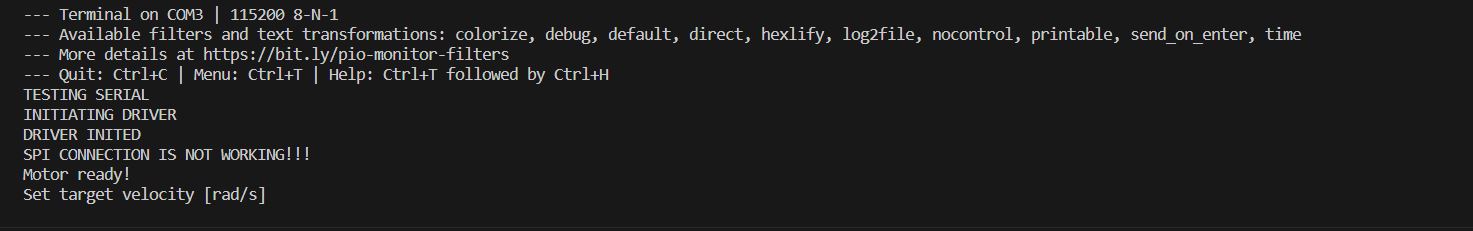
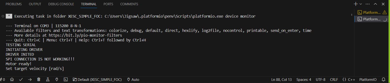
Serial.println("TESTING SERIAL");
SPI_1.begin();
delay(1000);
// driver init
Serial.println("INITIATING DRIVER");
delay(1000);
driver.init();
delay(1000);
Serial.println("DRIVER INITED");
delay(1000);
pinMode(faultIn, INPUT);
pinMode(ledPin, OUTPUT);
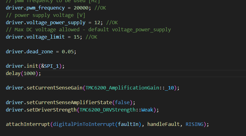
// pwm frequency to be used [Hz]
driver.pwm_frequency = 20000; //OK
// power supply voltage [V]
driver.voltage_power_supply = 12; //OK
// Max DC voltage allowed - default voltage_power_supply
driver.voltage_limit = 15; //OK
driver.dead_zone = 0.05;
driver.setCurrentSenseGain(TMC6200_AmplificationGain::_10);
driver.setCurrentSenseAmplifierState(false);
driver.setDriverStrength(TMC6200_DRVStrength::Weak);
attachInterrupt(digitalPinToInterrupt(faultIn), handleFault, RISING);
// link the driver with the current sense
current_sense.linkDriver(&driver);
// init current sense
current_sense.init();
//Validating the TMC6200 SPI Connection
//You can validate the SPI connection by checking the value of VERSION field in IOIN register. The value should be 0x10.
if(driver.getInputs().VERSION != TMC6200_VERSION){
// something is wrong with the spi connection
Serial.println("SPI CONNECTION IS NOT WORKING!!!");
}
Serial.println("Motor ready!"); //OK
Serial.println("Set target velocity [rad/s]"); //OK
delay(1000);
// limiting motor movements
motor.phase_resistance = 2.2; // [Ohm] //OK
motor.current_limit = 2; // [Amps] - if phase resistance defined //OK
motor.velocity_limit = 5; // [rad/s] cca 50rpm //OK
// link the motor to the driver
motor.linkDriver(&driver); //OK
// link driver and the current sense
// link the motor to current sense
motor.linkCurrentSense(¤t_sense);
// set control loop type to be used
//motor.controller = MotionControlType::velocity;
motor.controller = MotionControlType::velocity_openloop;
// initialize motor
motor.init();
//motor.initFOC();
// add target command T
command.add('T', doTarget, "target velocity");
command.add('C', doLimitCurrent, "current limit");
motor.foc_modulation = FOCModulationType::SinePWM;
// limiting voltage
motor.voltage_limit = 3; // Volts
// or current - if phase resistance provided
motor.current_limit = 0.5; // Amps
}
void loop() {
faultState = digitalRead(faultIn);
if (faultState == HIGH)
digitalWrite(ledPin, HIGH);
else
digitalWrite(ledPin, LOW);
// velocity control loop function
// setting the target velocity or 2rad/s
motor.move(); //OK
//motor.monitor();
command.run();
}
I tested it many times and cannot fix it. Triple checked my pin configs.MCU never talks to TMC driver. Since i couldn’t find any examples i used README on github library to generate main.cpp. Could someone point me in right direction?