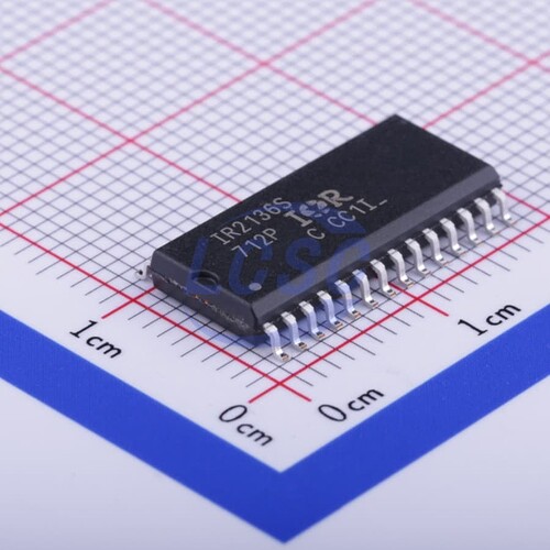
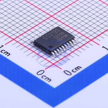
Huh, you’re right, I got confused by the Chinese datasheet - the one linked by LCSC seems to indicate 300V and either 20 or 25V for VCC, depending on which part of the datasheet you look at…
In any case, the INA2181 has 26V common mode range, and the FETs are labeled 30V, so I don’t think its a high voltage design…
I would not try anything beyond 24V, and probably stay on 12v just in case. There is just not enough silicon, literally, to support such high voltage. The driver is so small, compared to 600v Infineon 3-phase drivers, which are physically gigantic in comparison. You need a lot of extra silicon circuitry to achieve 600V designs.
Infineon 600v driver 3-phase
EG Micro driver 3 phase
Thanks! Of those it seems only the UNI and EG ones are in stock, so I’ll give UNI a try.
Me too in general. I’ve used them a lot as well (and compared to HTY). HTY tends to be a bit more expensive on the sample side, but they are quicker in general and cheaper in series (once you hit about $800 at PCBWay). For example above board was $800 for 10 at PCBWay in 2/1/1/2.
Thanks, interesting site. Didn’t know of them yet.
It’s designed to work with 6S LiPo packs, protection features kick in at 26V. A 6S battery will run at 21-22V loaded, keeping some margin.
Yes, it makes more sense (to me) to take 5V from a collective source, as it’s only direct use is to power Hall sensors, the rest has LDOs so local conversion doesn’t gain much and adds cost, complexity and board area.
I’m hoping to get these down to a $25-30 level in reasonable quantities so they can be on the market for about twice that.
Just to see if I understand correctly. The hall sensors will be used to positioning. What impact does that have on the performance relative to sensorless ESC’s or magnetic encoders.
Obviously the resolution will be lower, but that might not be a big issue?
BR Andreas
Application dependent. The gist of it is that FOC and other sensorless techniques won’t work so well at low speeds (worst of all starting), high load variation during a single cycle or for holding position (servo-type behaviour). On the upside there’s nothing to break or buy on the motor side of things.
Of the sensors Hall are by far the most common. Also by far the cheapest (both the sensor and supporting electronics). Hall sensors allow a motor to start from 0 speed and deliver good torque right away. They also work at pretty high speed due to the low resolution. Note that they measure phase position, not shaft revolutions / position. Encoders tend to measure shaft rotation, optionally absolute. Encoders work great for positioning and starting, but get expensive and unreliable real fast if you still want that accuracy at high RPM.
There is no right answer when it comes to this. It really depends on what you want to use your motors for.
Another excellent feature of hall sensors is that they’re placed off-axis, so you don’t need a perfectly sized through-hole encoder or access to the shaft end like a magnetic encoder. And measuring motor shaft position is fairly useless if you have a gearbox, so I don’t really consider that to be a disadvantage.
One thing I’ve been wanting to try with hall sensors is high resolution position estimation by using the past few sensor state time intervals to estimate the velocity and acceleration of the motor, and extrapolate that over the time since the most recent sensor change. Won’t work at near-zero speed, but should allow proper FOC once the motor is turning.
I’d also like to add compensation for imperfect sensor positioning, by slowly rotating the motor and recording the exact electrical angle fed to the coils when the sensors change. It’s a challenge to get the sensors positioned accurately enough on tiny motors, and I have some skateboard type motors where the sensors don’t look like they’re positioned quite right. Not sure if it’s just poor manufacturing, or to try and improve the timing if you’re using an ESC without timing adjustment. Though that seems like a crap shoot because depending on which way the motor turns to go forward, you may have the timing doubly off…
Are you working on a quadruped? That’s the first thing that comes to mind for 12 BLDC motors with current sensing ![]() I’d love to build one of those if I weren’t already busy with an even more exciting project. Though I want 14 motors, adding a third segment to the hind legs like just about every real four-legged animal.
I’d love to build one of those if I weren’t already busy with an even more exciting project. Though I want 14 motors, adding a third segment to the hind legs like just about every real four-legged animal.
Good point, yes!
This is for an AUV design (underwater robot), to do thrust vectoring. But I suppose they’d work equally well for legged robots.
Quick update on the ESP32s: My batch was shipped! They have some left in stock, but at much higher prices (still not STM32 territory though).
Ah, ocean exploration is indeed awesome as well.
If you haven’t seen it already, check out Nanoparticle’s thread on the use of linear hall sensors. That eliminates the need for my position extrapolation idea. And since it only uses two sensors, you can simply bend them closer or farther from eachother until the sine waves are exactly 90 degrees apart. With regular halls you have three of them to get precisely spaced, plus you have to position them precisely relative to the stator so the sensor state changes happen at the right time for commutation. Much more difficult.
Did this one work? Is the Kicad available anywhere?
Are you happy with the capacitor values on your voltage reg. 78L10G-AB3-R has different capacitors (0.33u and 0.1u). Also you have two LDOs both doing 3.3v - looks like one for analog. Is that because you need 200ma or trying to keep voltage separate? I usually see designs with ferrite beads separating 3.3v and 3.3vA.
Not sure what load you are expecting, but bulk capacitors are popular on high amp boards. (Edit - just seen your army off 22uf!)
No antennae - an esp32 without wifi makes me sad.
Looks like a lovely board btw.
Dear Stefan.
I absolutely love your design, I’m aware I might be 3 years too late.
But is there any chance you could make the kicad or any files like that available so people could recreate your amazing design.
I have been looking for a compact motor controller setup that includes phase shunts for months now and I can not really seem to find anything apart from this.
I am in the process of making a entomopter with 4 wings, with movement based on lineaire motors which like you can imagine need to be as light as possible.
I would love to hear from you.
All the best kim
I’d love to hear more about your project… and need to share more about mine too ![]() Which is an ornithopter with 4 motors per wing (3-axis shoulder plus wing extension).
Which is an ornithopter with 4 motors per wing (3-axis shoulder plus wing extension).
If @StefanH doesn’t return, you could check out my Gooser tileable dual-motor driver, which I think has finally reached a viable design after many failures. Similar size per motor, and hopefully higher current. The current sensors are hall-effect rather than shunts, but same result.
Hi Kim! Here’s a git copy of the design:
This design was a result of the supply chain issues with ST and while working on the firmware that mostly worked itself out (the imho far superior STM32G4 got cheap and available), so the project was dropped for a more suitable MCU (and more importantly more mature software stack).
In all honesty, I would not waste my time on fitting a square peg (ESP32) in a round hole (motor control) with alternatives not that much more expensive. Right now, if I’d do a low-cost quad ESC suitable for FOC I’d probably use the STSPIN32G4 (if low-side shunts are ok for you).
Hi Stefan
Thank you for sharing your design and ideas.
Yes I’d ended up running into the b-g431-esc1 which seems like it meets all my needs, also in size.
The only thing now will be to try and apply hfi to that board, since for my application there is no space for a encoder. Which will be a challenge but that is why where here

