I have been working with SimpleFOC for a while now to develop a custom PCB motor. After a few iterations I’m getting closer to what I want but ran into an issue that I have been struggling with. I have the following boards ArduinoMega2560 and ESP32 and DRV8311H. Running my code on the Arduino works exactly as I want with no issues. However the same code on the ESP32 produces a clicking sound. The time between clicks is dependent on the target velocity. I bought a cheap oscilloscope to try and diagnose the issue further but I’m not sure I’m using it properly. I plan to move to a STM32 chip in the future but I worry that this issue will continue. My question for the clever folks out there: what differences between the ATMEGA2560 and ESP32 could be causing this discrepancy? I tried the driver pwm frequency setting at both 40k,32k, and 400hz with no luck. Thank you in advance.
// Open loop motor control example
#include <SimpleFOC.h>


// BLDC motor & driver instance
// BLDCMotor motor = BLDCMotor(pole pair number);
BLDCMotor motor = BLDCMotor(11);
// BLDCDriver3PWM driver = BLDCDriver3PWM(pwmA, pwmB, pwmC, Enable(optional));
BLDCDriver3PWM driver = BLDCDriver3PWM(11, 10, 9, 8);//Arduino pins
//BLDCDriver3PWM driver = BLDCDriver3PWM(25, 26, 27, 33);//ESP32 pins
//BLDCDriver3PWM driver = BLDCDriver3PWM(PA10, PA9, PA8, PA11);


// Stepper motor & driver instance
//StepperMotor motor = StepperMotor(50);
//StepperDriver4PWM driver = StepperDriver4PWM(9, 5, 10, 6,  8);


//target variable
float target_velocity = 3.0;

float reverse = 1.0;
//Start timer to follow millis()
unsigned long myTime;
//Create point to start a duration
unsigned long resetTime;
//Time since last reset point
unsigned long duration;

//Create floating point time variable
float timer;

// instantiate the commander
Commander command = Commander(Serial);
void doTarget(char* cmd) { command.scalar(&target_velocity, cmd); }
void doLimit(char* cmd) { command.scalar(&motor.voltage_limit, cmd); }

void setup() {

  // driver config
  // power supply voltage [V]
  driver.voltage_power_supply = 5;
  // limit the maximal dc voltage the driver can set
  // as a protection measure for the low-resistance motors
  // this value is fixed on startup
  driver.voltage_limit = 5;
  driver.init();
  // link the motor and the driver
  motor.linkDriver(&driver);
  driver.pwm_frequency = 500;//added this to try and fix the issue, did not help
  // limiting motor movements
  // limit the voltage to be set to the motor
  // start very low for high resistance motors
  // current = voltage / resistance, so try to be well under 1Amp
  motor.voltage_limit = 5;   // [V]

  // open loop control config
  motor.controller = MotionControlType::velocity_openloop;

  // init motor hardware
  motor.init();

  // add target command T
  command.add('T', doTarget, "target velocity");
  command.add('L', doLimit, "voltage limit");

  Serial.begin(115200);
  Serial.println("Motor ready!");
  Serial.println("Set target velocity [rad/s]");
  _delay(1000);

  myTime = millis();
}

void loop() {

  // open loop velocity movement
  // using motor.voltage_limit and motor.velocity_limit
  // to turn the motor "backwards", just set a negative target_velocity
  myTime = millis();
  //convert time to floating point
  //timer = myTime*1.0;
  duration = myTime - resetTime;
  timer = duration*1.0;
 target_velocity = 0.5;

//  if(duration < 15000)
//   {

//     //Use floating point timer to increase target velocity
//     target_velocity = 4.5*(timer/15000.0)*(reverse);
//   }
//   if(duration>30000 && duration<45000)
//   {
//     target_velocity = 4.5 * (reverse);
//   }
//   if(duration>45000)
//   {
//     target_velocity = 0;
//     reverse = reverse * (-1.0);
//     resetTime = millis();
//     //target_velocity =4.5 - (4.5*((timer-45000.0)/30000.0));


//   }

  motor.move(target_velocity);

  // user communication
  command.run();
  Serial.println(target_velocity);
  //Serial.println(reverse);
}
There was a recent over-flow issue, could that be it? Every time some internal counter overflows, you hear a clicking. Reason is probably difference in the internal esp32 and atmega number formats.
I’m citing from memory, could be wrong. It’s annoying but harmless. I think @runger fixed it, or may be that’s a new one?
Did you set lib_archive=false build flag? this is required for the PWM hardware to be selected properly, that could by why changing the PWM frequency did not adjust anything for you.
Hi. Unfortunately I still have my “Arduino IDE” training wheels on. Are build flags a feature of PlatformIO? Is it possible to achieve the same thing using Arduino IDE?
Unfortunately not. The sound is still present. However I did notice that unplugging coils individually changed the sound. All 3 motor windings connected to the driver produced the fastest clicking. Only 2 motor windings connected produced a slower clicking. 1 motor winding connected produced no clicking. It is not anything to do with the rotation. I can get the clicking sound just buy holding a single magnet on top of a coil with my finger.
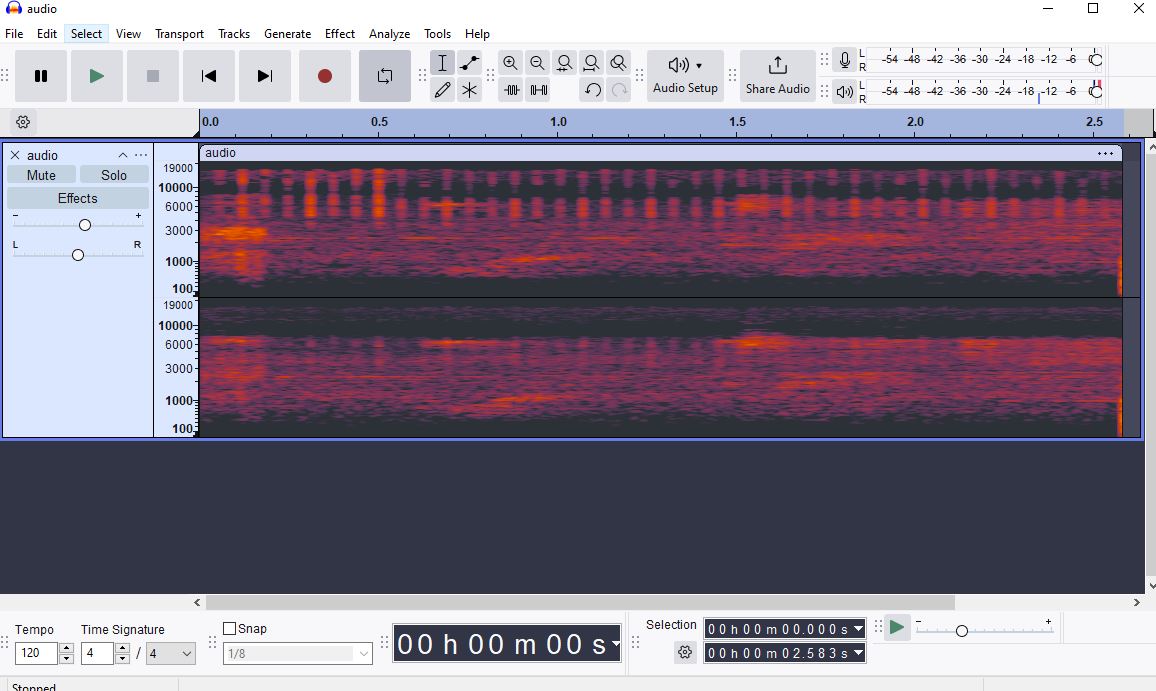
I tried my best to get a video of the offending ESP32 clicking. The video is hard to hear but I managed to isolate it better with audacity. Here is the YouTube link to the videoVideoLink. Clicking happens at 0:30. I tried to isolate and amplify the audio the best I could. I also attached the waveform output from audacity. I think that the bars seen at regular intervals show the clicking.
the clicking only happens in the presence of a magnet
The clicking sounds to me like it’s of a mechanical nature, like as if the stator PCB is vibrating on the table? Because the PCB is light, maybe it’s lifting itself off the table?
Does it go away when you tape it down?
But why is it only happening with the ESP32?
Which board definition are you using for this MCU board?
-Yes. I am on my 3rd prototype. I tried to design for 5v and 1 amp.
-Much less sound at least. There is still some whining with the ATMEGA. But it is much quieter.
-Yes. I am using the board I linked earlier. I use almost the exact same code except for new pin definitions
-There is no sound at all when the magnet is removed. Disconnecting a motor wire from the PCB has the effect of slowing the rate of clicking. Disconnecting a second wire removes the clicking entirely since the circuit cannot close now.
-I can still get the sound when holding the PCB in my hand. I think any sounds are between the magnet and the PCB not the table. I am holding the magnet to the PCB quite firmly. I don’t think it is strong enough to jump around under my finger.
-I would like to try it on STM32. Unfortunately I misjudged the file size and cannot upload to my board with limited flash.
-I am using the Esspressif board library “ESP Dev Module”
I would like to try changing the PWM frequency to see if that changes anything. A previous comment from “VIPQualityPost” seems to imply that I missed a step when trying this previously. Unfortunately I am not familiar with the use of build flags. I assumed that I could just include the line “driver.pwm_frequency = 500;” into my setup to change the frequency. I am not sure if it is working properly and the oscilloscope I bought doesn’t seem up to the task.
Sorry, I lost track of this thread… did you solve the issue?
From my point of view, your coils and the magnet are interacting to cause this sound. It looks to me like it maybe has more to do with the commutation speed than the PWM frequency, so you could see if running the stator at different different speeds causes different frequencies of sound.
You can also set the pwm frequency to check that theory.
That’s correct, that’s all you have to do, before calling driver.init(). The frequency is in Hz, so 500 is way too low. Something like 20000 or 30000 is a better value.
That’s weird. There must be some kind of difference, are you running the motor at the same speed in both comparisons?
In the end, it could even be something like the PCB flexing by tiny amounts due to the magnetic forces - if you can make something vibrate, then you have a speaker… I’m guessing if you taped everything down with double-sided tape then the issue would also be less or go away. But the real question is whether it matters? During operation, there will be a rotor which can spin and not a magnet pressed against the stator. So maybe this isn’t an issue during normal operation?
@runger
Hey no problem. I was able to make some progress recently. The frequency issue was a silly mistake. I was calling driver.pwm_frequency after driver.init which caused the issue of not being able to change PWM frequency on both boards. However this didn’t solve the issue. Lower frequency values (<20k) start causing the coils to whine. Values from 2k - 20k provide a range of different sounds on the ESP. Greater than 20k all sounds the same to me. Interestingly the ATMEGA was making some ticking when I used the 400hz setting instead of 32khz.However I still can’t nail down the ticking.
Stator speed has the effect of changing the frequency between ticks. But it does not change the pitch of the tick.
Both boards use the same code aside from some different pin assignments. I really can’t find a significant difference between the two. I don’t think that the logic voltage level could really cause any difference with the driver I am using.
The noise is still present during normal operation with a spinning rotor. That’s how I first noticed it.
I was thinking of making some kind of magnetic field measuring device using some linear hall sensors to try and measure the fields produced by the two boards. But I might get lazy and just switch everything over to the ATMEGA chip to get over the issue.
No, I didn’t expect it to change the pitch, I meant the frequency of the click events… so that’s confirmed that what you’re hearing is related to the commutation.
So changing the PWM frequency you would not expect it to have a big effect then.
Does this mean ATMega and ESP32 aren’t using the same stator PCBs? What if you switch the two stators?
My guess is that the stator is vibrating in some way - the fields it is creating push on the magnet, but this also can be seen as the magnet pushing on the PCB. Maybe this is causing the vibration.
If you have a spare stator you could try to epoxy it to something solid, to prevent it from flexing/vibrating, and see if it still makes any sound or the sound is reduced?
I think someone else(an angel from heaven) solved the problem for me.(will probably never happen agian… ) I found this post on the GitHub page with the same exact problem. Turns out I had the voltage configured incorrectly. The motor voltage should only be half of the supply voltage in order to avoid issues. Implementing the changes from that thread fixed the ticking issue. However I am still a little confused by all of the voltage items. I wanted to design my PCB motor to run on a 5v USB supply. If I am understanding this page correctly I would need a motor voltage limit of 2.5v. Could you help me understand the difference between driver.voltage_power_supply, driver.voltage_limit , motor.voltage_limit?
Yeah, it’s really confusing and bit me the other day too. It’s sort of like signed versus unsigned integers. The driver voltage is “unsigned” and gives the total range you have to work in. The motor is “signed” and ranges up/down from center, so its absolute value can only be half of the total range. Uq is multiplied by sine/cosine, which are -1 to +1 so the range sort of gets doubled.
With SVPWM modulation, there are points where you can have one phase 0V and another phase equal to driver voltage, and third phase at the midpoint.
The driver voltage limit is mostly only useful if you’re using the driver class directly to drive the FETs without any of the motor classes. Normally it just adds confusion and performance overhead, so personally I’d rather remove it.
I’m glad you found it, but it’s still not clear why overmodulation would cause the audible clicks…
But I guess the important thing is that it’s fixed.
Well, there are edge cases when it is useful. Many gate drivers can’t handle 100% duty cycle so the driver limit is one way to ensure that there is a maximum duty cycle <100%.
You might also be interested in limiting the maximum voltage (taking into account spikes) to some value below the supply voltage to prevent damage to the power supply if the motor suddenly stalls or similar.
Or your motor may just not be rated to the voltage of your PSU.
And if you want to overmodulate the waveform, for whatever reason, having a driver limit allows you to do so without hitting the supply voltage.
But I agree, for normal purposes usually you’re going to want to use the motor limit.