Some thoughts on current sense and current limiting a stepper.
Now that I have some current readings to look at (see below). I’m starting to wonder how the current limit is implemented. Let’s say a certain stepper has a current rating of e.g. 4amp. That’s a typical low resistance NEMA23.
When calculating the PWM duty cycle, then that current limit variable is taken into account with the other variables like resistance, inductance, voltage limit etc.
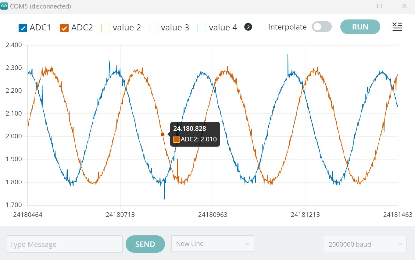
The reason why I’m bringing this up, is looking at the current/voltage waves, it is obvious that the current is not constant, it’s a wave. Thus we can’t compare the usual stepper current rating, since that will actually send the full current limit to the winding while stepping/micro stepping.
Using FOC typology it should therefore be possible to exceed the current rating, or we should somehow calculate the average current flow and use that as the limiting factor.
One way to do that would be by taking x measurements on the half-wave and do the average by / x. When the measurement trips the zero point (sensor centro) we then know when to start a new average calculation?
I see there are several methods for stepper FOC control. In this article they also mention this feed forward concept we have been hearing about. I’m not saying I can just implement this method like that…
The proposed method is in the form of an FOC even though DQ transformation is not used. Thus, the proposed method can reduce the necessary computation required of the processor used to implement the control scheme
interesting article, I have to admit it’s a bit hard to understand. It is not entirely on my end, that they have to talk about the “DQ” transformation instead of just calling it the Clarke transform, and never clearly define what they mean exactly by FOC is not very good writing, really. A good peer reviewed article should actually be written well enough for laymen to understand.
However it appears to be implementing much the sort of thing I was thinking of, in which the characteristics of FOC drive as it is usually defined are mostly captured, not by measuring the phase currents but by indeed feed-forward compensation of the voltage waveform, compensating for what are known to be distortions in the current waveform from the ideal when plain old 3 phase sine wave voltage at the right phase shift is played out the terminals. It’s not quite clear exactly what kind of distortions they are expecting, though. I would expect the various inductances and magnetic properties would be the main thing to compensate for, as inductance of the motor would probably be the primary cause of the current waveform getting messed up but I don’t see inductance mentioned anywhere in there. They seem to be employing some kind of linear adjustment to the phase shift as the frequency increases, or something.
Seeing how well the current waveforms are similar to the voltage waves I understand the reason for looking to this feed forward concept, which may stabilize the velocity in a different way.
Nonetheless it would be cool to do the experiment so that we can compare the performance, for future reference…
This is taken from BLDCmotor.cpp:
// update the controller limits
if(current_sense){
// current control loop controls voltage
PID_current_q.limit = voltage_limit;
PID_current_d.limit = voltage_limit;
}
Maybe I will answer original question.
If your current is roughly a sine wave then just use calculate RMS current. RMS is precisely the concept invented for making alternating current values interchangeable with DC values.
If you have +/-4amp peak current, then the RMS is 4/sqrt(2) =2.8A. Then indeed, if rated current is 4amp per phase (DC stall torque current) then you can have higher peak alternating current - continuously.
In the context of FOC, your Iq current is in the realm of RMS as well, so keep the Iq current under 4 amp if you want to drive the motor continuously under load with this kind of current.