/**
 *
 * Velocity motion control example
 * Steps:
 * 1) Configure the motor and magnetic sensor
 * 2) Run the code
 * 3) Set the target velocity (in radians per second) from serial terminal
 *
 *
 * By using the serial terminal set the velocity value you want to motor to obtain
 *
 */
#include "SimpleFOC.h"

#define EN_GATE 8
#define M_PWM A1
#define M_OC A2
#define OC_ADJ A3

// The cs is Pin7,board is simplebgc mos v1.3
MagneticSensorSPI sensor = MagneticSensorSPI(7, 14, 0x3FFF);

// magnetic sensor instance
// MagneticSensorSPI sensor = MagneticSensorSPI(10, 14, 0x3FFF);

// magnetic sensor instance
//MagneticSensorI2C sensor = MagneticSensorI2C(0x36, 12, 0x0E, 4);

// Motor instance
// BLDCMotor motor = BLDCMotor(9, 5, 6, 7, 8);

// Motor instace(Simplebgc v1.3) (MOT1 9,10,11;MOT2 3,5,6)
BLDCMotor motor = BLDCMotor(3, 5, 6, 14, 8);

void setup() {

  // initialise magnetic sensor hardware
  sensor.init();
  // link the motor to the sensor
  motor.linkSensor(&sensor);

  // DRV8302 specific code
  // M_OC  - enable overcurrent protection
  pinMode(M_OC,OUTPUT);
  digitalWrite(M_OC,LOW);
  // M_PWM  - enable 3pwm mode
  pinMode(M_PWM,OUTPUT);
  digitalWrite(M_PWM,HIGH);
  // OD_ADJ - set the maximum overcurrent limit possible
  // Better option would be to use voltage divisor to set exact value
  pinMode(OC_ADJ,OUTPUT);
  digitalWrite(OC_ADJ,HIGH);

  // power supply voltage
  // default 12V
  motor.voltage_power_supply = 12;

  // set motion control loop to be used
  motor.controller = ControlType::velocity;

  // contoller configuration
  // default parameters in defaults.h

  // velocity PI controller parameters
  motor.PI_velocity.P = 0.001;
  motor.PI_velocity.I = 0.2;
  // default voltage_power_supply
  motor.PI_velocity.voltage_limit = 12;
  // jerk control using voltage voltage ramp
  // default value is 300 volts per sec  ~ 0.3V per millisecond
  motor.PI_velocity.voltage_ramp = 1000;

  // velocity low pass filtering
  // default 5ms - try different values to see what is the best.
  // the lower the less filtered

  motor.LPF_velocity.Tf = 0.1;

  // use monitoring with serial
  Serial.begin(115200);
  // comment out if not needed
  motor.useMonitoring(Serial);

  // initialize motor
  motor.init();
  // align sensor and start FOC
  motor.initFOC(2.4666,CW);

  Serial.println("Motor ready.");
  Serial.println("Set the target velocity using serial terminal:");
  _delay(1000);
}

// velocity set point variable
float target_velocity = 0;

// utility function enabling serial communication with the user to set the target values
// this function can be implemented in serialEvent function as well
void serialReceiveUserCommand() {

  // a string to hold incoming data
  static String received_chars;

  while (Serial.available()) {
    // get the new byte:
    char inChar = (char)Serial.read();
    // add it to the string buffer:
    received_chars += inChar;
    // end of user input
    if (inChar == '\n') {

      // change the motor target
      target_velocity = received_chars.toFloat();
      Serial.print("Target velocity: ");
      Serial.println(target_velocity);

      // reset the command buffer
      received_chars = "";
    }
  }
}

void loop() {
  // main FOC algorithm function
  // the faster you run this function the better
  // Arduino UNO loop  ~1kHz
  // Bluepill loop ~10kHz
  motor.loopFOC();

  // Motion control function
  // velocity, position or voltage (defined in motor.controller)
  // this function can be run at much lower frequency than loopFOC() function
  // You can also use motor.move() and set the motor.target in the code
  motor.move(target_velocity);

  // function intended to be used with serial plotter to monitor motor variables
  // significantly slowing the execution down!!!!
  // motor.monitor();

  // user communication
  serialReceiveUserCommand();
}
Hey @Leonardo, I am very happy to see that you were able to have some results.
I’ve just made a small calculation and I think you are hitting the processing limit of the atmega328 chip.
So average time of one loop() function with magnetic SPI sensor is arround 1ms:
Your motor has 14 pole pairs which means that each
360/14 = 25.7 degrees ~ 0.44 radians
you do the full electrical rotation. To be able to turn your motor you will need to be able to detect, at least once, per 120 electrical degrees. What is:
25.7 * 120/360 = 8.57 degrees ~ 0.149 radians
And when you are running your code with velocities such as: 30rad/s
30 rad/s * 1ms = 0.03 radians ~ 1.71 degrees
Which means that for your velocity of 30rad/s you only have 8.57/1.71 = 5 discrete steps instead the sine wave. This may be the reason you hear so much noise when running this code.
One way to deal with this is to move to another microcontroller. For example STM32 bluepill.
Can you tell us what is the loop execution time when you run the exepriments?
Hi @Leonardo,
with a motor with 0.2 ohm and the DRV8302 board I suggest you to set at maximum motor.PI_velocity.voltage_limit = 3. I also suggest you to reduce motor.LPF_velocity.Tf = 0.01, because I noticed a strange movement of the motor at the end of the previous video.
About the noise problem, I agree with @Antun_Skuric. Try another microcontroller.
Good day,guys!
I am still a novice in programming, so I used this code to check the execution time of loop() .
  void loop() {
  unsigned int timecnt;
  // main FOC algorithm function
  // the faster you run this function the better
  // Arduino UNO loop  ~1kHz
  // Bluepill loop ~10kHz
  imecnt = millis()-timecnt;//Read once before testing the function,The unit is ms
  motor.loopFOC();

  // Motion control function
  // velocity, position or voltage (defined in motor.controller)
  // this function can be run at much lower frequency than loopFOC() function
  // You can also use motor.move() and set the motor.target in the code
  motor.move(target_velocity);

  // function intended to be used with serial plotter to monitor motor variables
  // significantly slowing the execution down!!!!
  // motor.monitor();

  // user communication
  serialReceiveUserCommand();
  timecnt = millis()-timecnt;//Subtract the last result after the function test is completed
  Serial.print("timecnt=");//print the "timecnt"
  Serial.println(timecnt );
}
timecnt= 47-50 (ms)
In fact, I should have used ARM framework chips early, and besides testing Arduino this week, I have also been trying to use Arduino on ARM chips. I still have no success until today,
This is a STM32F103C8T6 128K mini board, I downloaded it through the serial port
generic_boot20_pc13.bin
and the flashing light is like this, Isn’t it an interval of one second? And the LED of PC13 will go out eventually.
The IDE I use is PlatformIO, I have created a new bluepill_f103c8_128k
project, but it never succeeds when uploading through the serial port.
This is my PlatformIO.ini
configuration file
; PlatformIO Project Configuration File
;
;   Build options: build flags, source filter
;   Upload options: custom upload port, speed and extra flags
;   Library options: dependencies, extra library storages
;   Advanced options: extra scripting
;
; Please visit documentation for the other options and examples
; https://docs.platformio.org/page/projectconf.html

[env:bluepill_f103c8_128k]
platform = ststm32
board = bluepill_f103c8_128k
framework = arduino
upload_protocol = serial
upload_port = /dev/cu.usbmodem14101
No need to use Roger’s bootload any more. Go to the link above!
In fact, "Arduino_ Core_ STM32 “is relative to” Arduino "_ AVR ", it’s too powerful;
However, when you use the standard STM32 (ARM) tools, such as cubmx, KEIL, IAR for programming, the “Arduino” tool can be put down!
@Owen_Williams Hi,Thank you for your answer. Finally, I used Nucleuo-64,I download firmware through stlink, and serial communication. Now I’m still trying to debug
@blackblue007 You are right. At first, I planned to compile the program through keil under the standard arm framework, but I saw that simplefoc is based on Arduino framework, so I want to try it .
The loop() speed of Arduino execution on the board 50ms(50000us)
When I used Nucleo-64, the loop()execution time was to 122us!!
Unfortunately, The motor still make noise when I use the Nuclear-64 to turn the motor(>30rad/s)
Are you limiting the voltage_limit? What is the nominal voltage/current of you power source?
In my opinion, that noise is the result of the current required by the motor from the power source that exeeds the limits. With a resistance of 0.2 ohm, at about 30 rad/s (290rpm), with a motor of 180 KV, it means that motor requires about 1.6V. At 1.6V, your motor draws about 8A!
Everything I have said is not very correct as there are many approximations, but in general I think it is correct reasoning
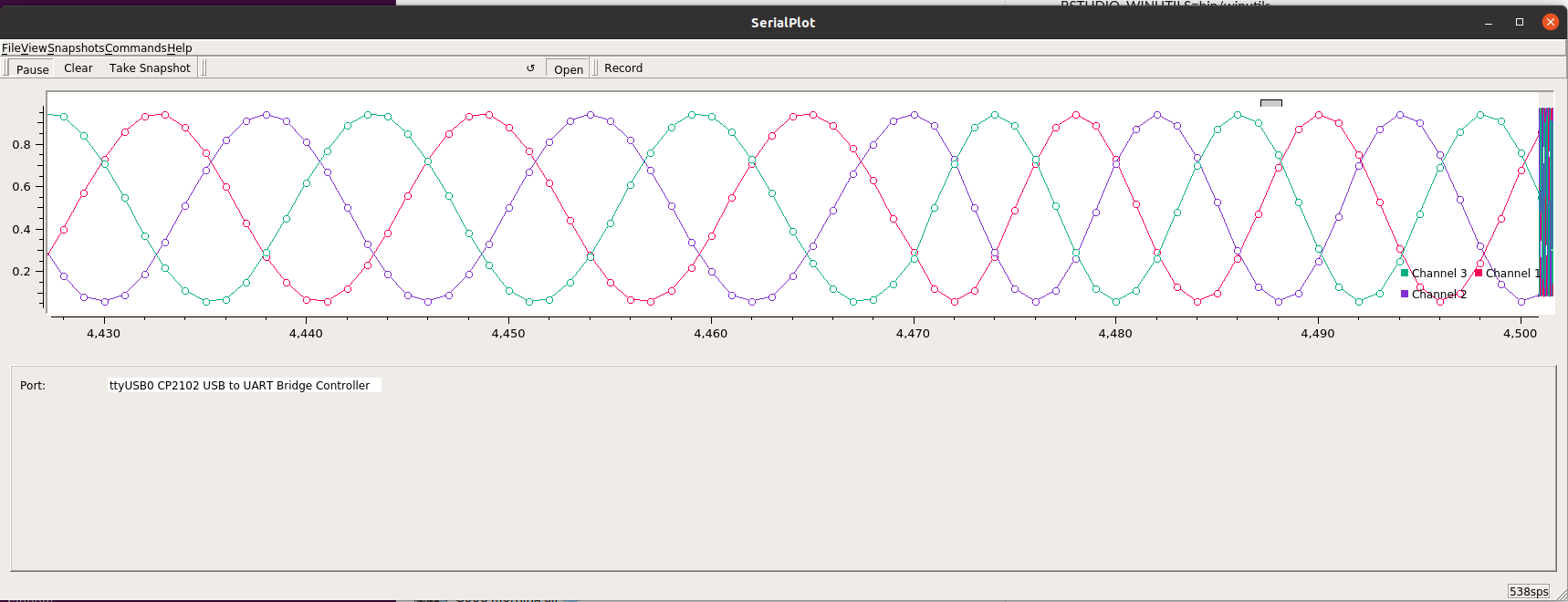
I’ve tried to repeat @Leonardo’s issue and seen something similar
This is on velocity_openloop with a relatively high voltage of 4v. It starts juddering at 35ish rad/s. If i drop the voltage limit to 2v it starts happening at about 17 rad/s. This is a large gimbal (10 ohm) and is drawing steady 300ma when ok and 100-500ma when not ok. 9v power supply.
In my case i think it’s simply a case of spinning electric angle quicker than current can keep up with.
It’s very hard to see but about 60% of the way through I swap from 30rad/s to 40rad/s.
Looks pretty normal.
There aren’t many points in each electrical rotation - in reality the motor is seeing steps not the lines drawn between the points. The few points here could be a factor. also the atmega328p isn’t doing center aligned PWM - if we looked at it with an oscilloscope we might see that the left aligned PWM is messing up at this speed.
I think there is a separate bug here or perhaps the way voltage_limit works is unintuitive. I’ve got a voltage_limit of 4v on a 9v power_supply. I’d expect just less than 50% power but its nearly at 100% power, isn’t it?
(If this is a bug it is likely just a problem with the new velocityOpenloop() function)
I agree that the number of points is probably the reason why this happens. But I need to investigate it a bit more deeply. Maybe it is also the resolution of the pwm.
Atmega328 does the center aligned pwm. The times are configured in FOCutils.cpp.
This is not a big. It is not intuitive maybe though. It depends how you look at this problem.
You are defining a dc voltage limit for an sinusoidal wave. So there is already an ambiguity there. Basically the voltage limit will set the voltage limit for the Vq. This is the q component of the clarke+park transformed voltage. The whole library uses this value as ‘voltage’ value it is stored in the variable voltage_q.
But this can be changed to limit the actual voltage set to the motor. But the problem is that then the centering needs to depend on this voltage limit. I am not really sure which one is less messy or more intuitive solution
I’m going to look at this a bit more later in the week. Probably on Friday or weekend. I did a quick test on my ESP32 with what I thought was the same setup and it was worse! It started misbehaving at 12 rad/s!
This makes sense for the open loop. Your rotor is skipping. But this should not in any way happen in the closed loop.
Can you make a video of the closed loop misbehaving maybe, once when you have time.
Im using different motors but I have a feeling that the esp32 version of the code needs a bit more love(Im not complaining:) . I did modify the frequency of the esp32 setup to be something other than the audible PWM it had by default but didnt help so much. Ill be back into these topics now that I am back:)
@Adam_Donovan. Good to hear you are getting back into it. When you have time, I’d like to hear a bit more about your setup and the issues you are having on esp32. Imho is a lot quieter and smoother than atmega326p.
At this point there is 3-4 different problems/issues that have been addressed in this topic and for most of them there isn’t enough details to conclude anything really.
So if there really is a problem, it would be really great if someone can reproduce it and show it in a video or some graph or expLain how to reproduce it.
This would make sure that we solve problem for the next library versions and nice people from this community would help you to resolve it as fast as possible.
So @Adam_Donovan, could you please give us a bit more info about the problems you are facing using the ESP32 version of the library.
And @Leonardo, could you please show us the exact behavior that you are trying to avoid. Maybe a video of it would be a good idea.