Its for a school project. You know how the early monks developed the herbal knowledge and refined the plants through, well trial and error. Lots of the old medical herbs we take for granted, so I thought it be wise to educate future generations in how the exes heat from STRONG lights, can be used to heat the living space and make herbs.
I see, no problem, I was just asking for a friend, purely research purposes.
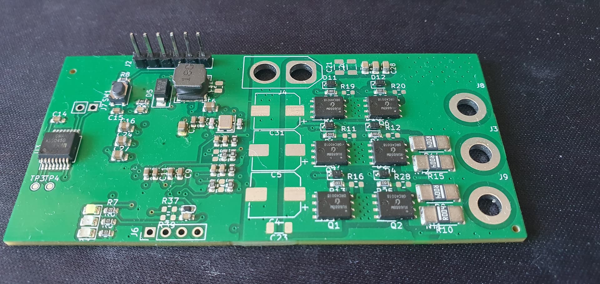
So the MT6835 BOB does sit nicely in the Molex connectors, but I suspect it will need a drop of some kind of bonding. By hand I can wiggle it from side to side, not to say that the motor vibration will shake it. Besides making it modular, the purpose is also to lift it towards the magnet, so in that sense it does a great job. The sensor is raised above the ceramic capacitors, which makes it possible to mount it to the motor without shorting those caps to the chassis. Of course the concept aligns the sensor very well.
By raising the sensor, it should also be possible to mount a flat heat-sink on the FETs pointing outwards, if necessary.


Thank you so much for your detailed documentation! I actually need to create a very similar project but it needs to run a NEMA 34 stepper motor at about 6A current at 430 RPM.
Do you think the MT6835 will have any benefit over a 12 or 14 bit sensor?
Since you are using a stepper motor and you added the two MAX40056 current sensors, are you actually able to use them? I thought the SimpleFOC library does not support current sensing for steppers
I’m working on INA241 TI current sensors. If you are interested in being part of the Beta test run, let me know. I ordered 30pcs PCBs for the prototype and they, so far, seem to work. In two weeks time, when I have some more testing done and some documentation, I will start to make that happen. Others are naturally welcome to join.
NEMA34 and 6 amp should not be a problem. All we need is a bracket for the larger dimensions.
But I’m confused because the SimpleFOC library does not support current mode for stepper motors, right? Are you working with a development branch that does?
As you might have seen I worked all night getting the MT6835 working. The current sensors are centered, so reading them is just a matter of code
Ok so you installed the hardware and are waiting until the library is updated with the code. But as of right now, you cannot actually use the feature
Why should I wait for that. The MCU has a working ADC? Getting it setup will probably involve the HAL
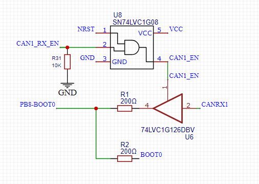
That board looks great! I’m also trying to bring up the STSPIN32G4. Nothing as fancy as your board. More a test board to get thing going. The micro is now running after some issues with the boot0 not being pulled up and the switch mode power supply letting out little bit of magic smoke. The ready and nfault are both low but don’t seem to be getting any action on the driver still. So still on the debugging path and it’s sure to be something silly. Really like the compact nature and hopefully simplicity of the STSPIN which you seem to have leveraged well. Best of luck with yours it looks super great.
I’m pretty sure they are pulled up. When you say smoke, is it then black smelly smoke or white cloudy smoke ?
Yes you are most correct, don’t know what I was thinking.
With my power supply issues the UVLO error triggered and they where pulled low. After resolving the power supply issue the UVLO alarm went away. The status register still had reset=1, which seems to be keeping the ready pin high. After writing to the clear error register that goes away and the ready pin goes low. Not sure what that’s about. Although I see st doing the same thing in the sample code along side setting the reset register.
The smoke was the white type, it was functional at 12v but not producing enough voltage on VCC. Increasing the voltage to 38 which removed that issue but after a few minutes a small amount of magic smoke was released. Not sure where it came from but didn’t expect to run it at 38v so likely exceed a maximum rating somewhere. Disabled the switch mode regulator and am now running VCC off 12v and I can’t think of anything wrong with that. Was hoping I could leave this issue till after getting a motor spinning but maybe will have to bring up the second board or swap out the chip to confirm I didn’t do any damage.
Hi Juan-Antonio_Soren_E
AndyMack from the OpenPnP Discord.
I’ve not used simpleFOC and have no direct experience with FOC - So its a learning curve for me.
How did you go with BOOT0 issue so far?
Helo and welcome to the SimpleFOC community!!
Don’t know, ok, it’s not a issue, I’m still debugging. Why?
Yes, true. I used the st-link for that. Haven’t tried changing it since. I don’t think it’s an issue though.
Dear Juan-Antonio,
I have a problem with my custom stspin32g4 board ( see photos attached).
I have tested with my MOSFETS and buck converter inductor.
The STSpin32g4 controller gets hot once I connect my MOSFETs, especially the GLS3 MOSFET.
The motor pilot goes to the STOP state whenever I click on start on the motor pilot, and the controller gets hots ( see video attached)
However, whenever I remove the MOSFETs, it goes to the START state on the motor pilot, and the controller doesn’t get hot.
I have checked for partial contacts and cannot find any within the PCB circuit.
My circuit was made exactly from the EVSPIN32G4 schematic.
I would be very happy if you could link me to the technical team of STSPIN32.
Thank you very much,
Mit freundlichen Grüßen - with kind regards
Aminu Bugaje

Motor pilot Video: video1804628762.mp4 - Google Drive
Cirucit: 06_04_2023_Motor_controller_PCB_Project2.pdf - Google Drive