Hello,
I am trying to get the Torque control option working, with the FOC Current Example using a Teensy 4.0.
I got the basic examples working, SPI AS5048 working with the teensy and the open loop position and velocity examples working.
Firstly I wanted to know if the FOC Current example is compatible with the Magnetic encoders and the only example is under the standard ‘encoder’. My test code where I have tried to implement this myself gives me the error of:
MOT: Monitor enabled!
MOT: Init
MOT: Enable driver.
MOT: Align sensor.
MOT: sensor_direction==CW
MOT: PP check: OK!
MOT: Zero elec. angle: 1.41
MOT: Align current sense.
CUR: No driver linked!
MOT: Align error!
MOT: Init FOC failed.
Motor ready.
Here is my code (*Written by myself so most likely an init issue by how I have called stuff)
- I have called sensor.init() twice for the magnetic sensor but this seemed to also work for the other examples so I kept it as is.
#include <SimpleFOC.h>
// BLDC motor & driver instance
BLDCMotor motor = BLDCMotor(11);
//BLDCDriver3PWM driver = BLDCDriver3PWM(9, 5, 6, 8); //UNO Pinout
BLDCDriver3PWM driver = BLDCDriver3PWM(4, 6, 5, 7); //Teensy Pinout
//MagneticSensorSPI sensor = MagneticSensorSPI(AS5048_SPI, 10);
MagneticSensorSPI sensor = MagneticSensorSPI(10, 14, 0x3FFF);
// current sensor
InlineCurrentSense current_sense = InlineCurrentSense(0.01f, 50.0f, A0, A2);
// instantiate the commander
Commander command = Commander(Serial);
void doTarget(char* cmd) { command.scalar(&motor.target, cmd); }
void setup() {
SPI.begin();
// initialise magnetic sensor hardware
sensor.init();
// link the motor to the sensor
motor.linkSensor(&sensor);
// initialise the current sensing
current_sense.init();
// for SimpleFOCShield v2.01/v2.0.2
current_sense.gain_b *= -1;
//current_sense.skip_align = true;
// set torque mode:
motor.torque_controller = TorqueControlType::foc_current;
// set motion control loop to be used
motor.controller = MotionControlType::torque;
// current sense init hardware
current_sense.init();
// link the current sense to the motor
motor.linkCurrentSense(¤t_sense);
// foc current control parameters (Arduino UNO/Mega)
motor.PID_current_q.P = 5;
motor.PID_current_q.I= 300;
motor.PID_current_d.P= 5;
motor.PID_current_d.I = 300;
motor.LPF_current_q.Tf = 0.01;
motor.LPF_current_d.Tf = 0.01;
// driver config
// power supply voltage [V]
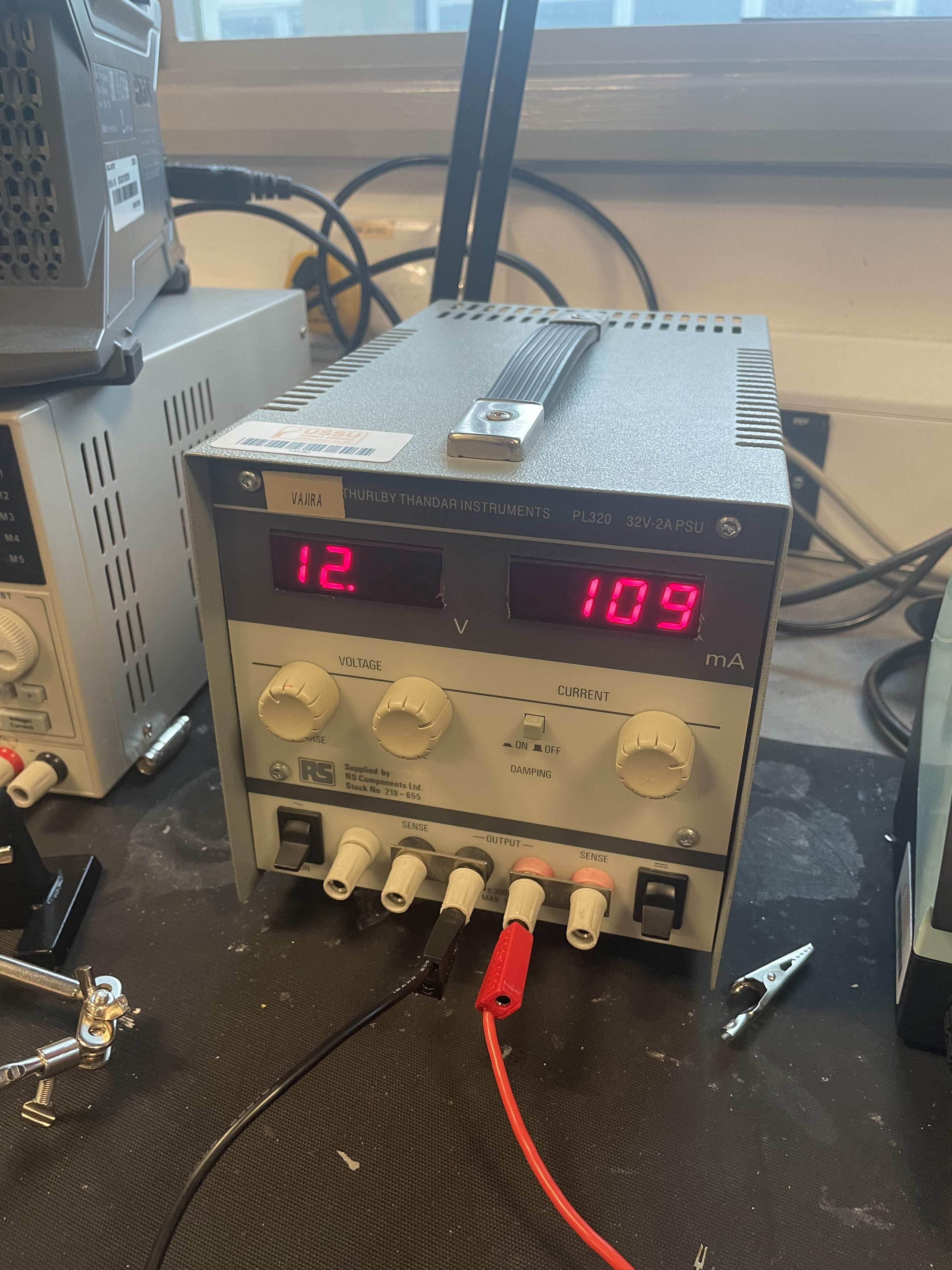
driver.voltage_power_supply = 12;
driver.init();
// link driver
motor.linkDriver(&driver);
// use monitoring with serial
Serial.begin(115200);
// comment out if not needed
motor.useMonitoring(Serial);
SimpleFOCDebug::enable(&Serial);
// initialize motor
motor.init();
// align sensor and start FOC
motor.initFOC();
// initialise magnetic sensor hardware
//sensor.init();
// add target command T
command.add('T', doTarget, "target current");
Serial.println(F("Motor ready."));
_delay(1000);
}
void loop() {
float current_magnitude = current_sense.getDCCurrent();
Serial.print(current_magnitude*1000); // milli Amps
Serial.print("\t");
//Magnetic Encoder
sensor.update();
// display the angle and the angular velocity to the terminal
Serial.print(sensor.getAngle());
Serial.print("\t");
Serial.println(sensor.getVelocity());
// main FOC algorithm function
motor.loopFOC();
// Motion control function
motor.move();
// user communication
command.run();
}
Any help would be appreciated, especially any stupid errors on my part.
Overall I am creating a CubeSat reaction wheel, so hopefully an IMU angle reading can be fed into the position control method and rotational velocity can be fed into the velocity control method for attitude control and de-tumbling.
I am only doing a 1-axis reaction wheel and have access to a 1-dof setup/testing system.
Here is my setup:
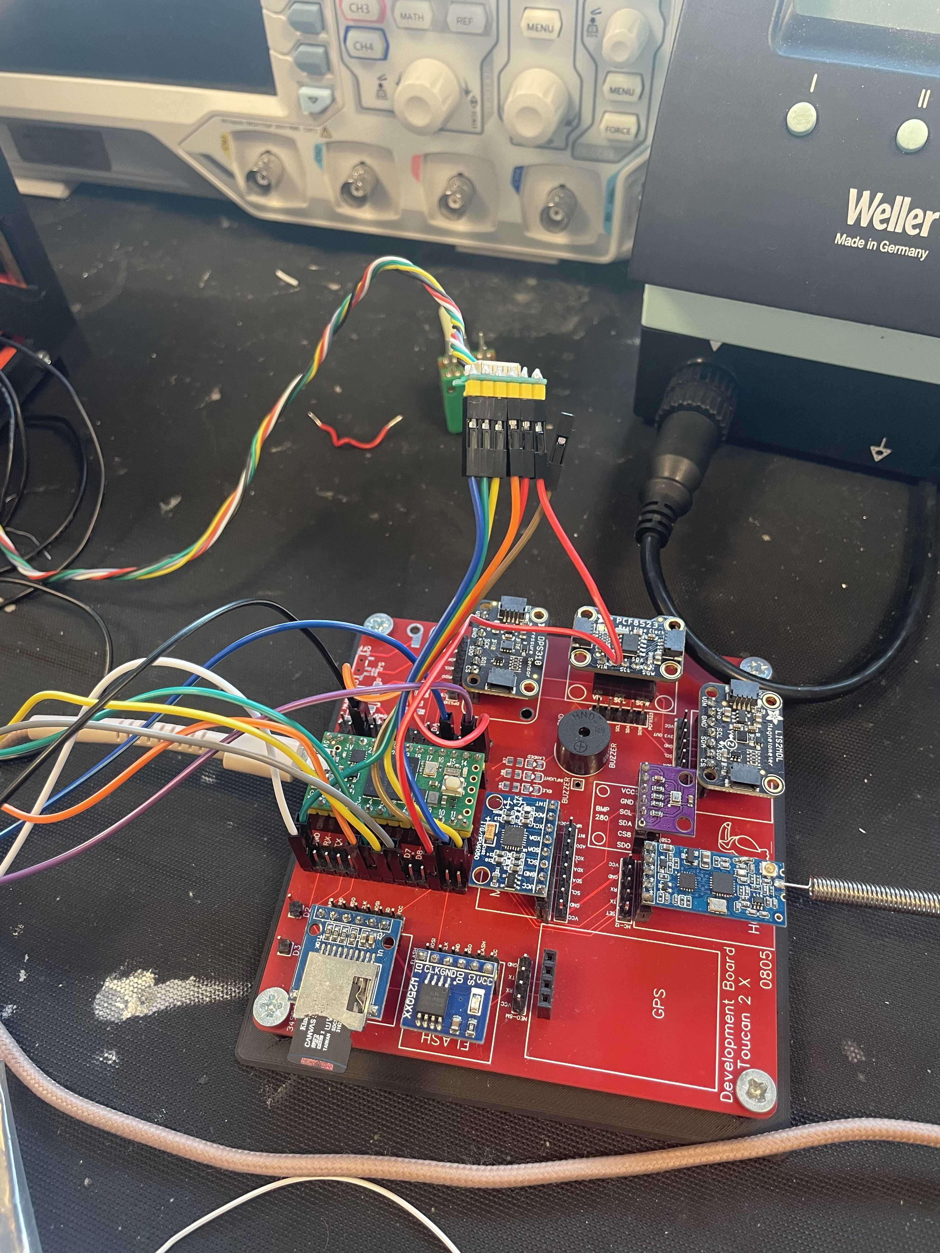
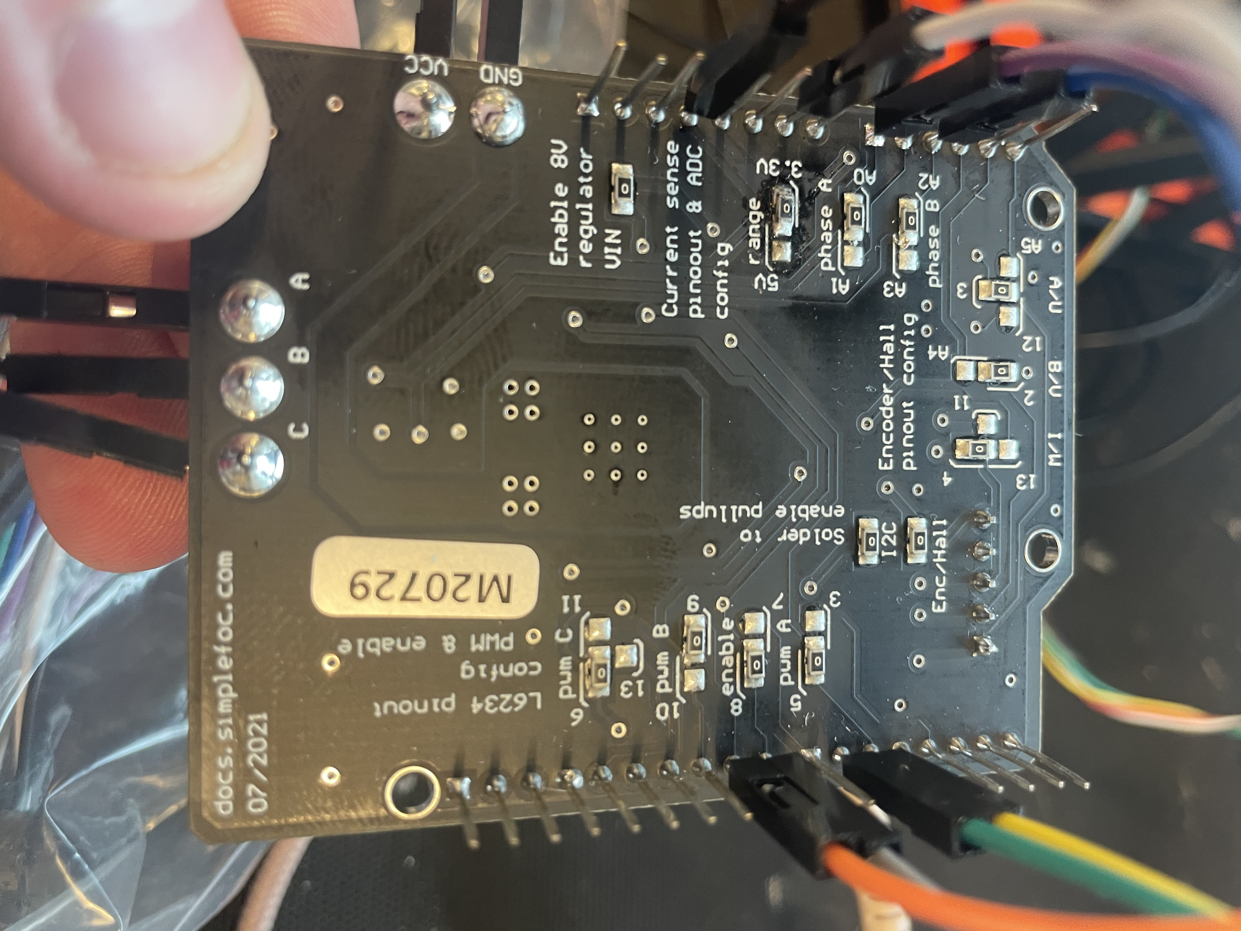
The AS5048 works correctly, so the SPI pinout works, the purple and blue wires are A0 and A2 respectively and I have connected the GND and 3.3V between boards as the teensy is 3.3V logic level, and have changed over the 0 Ohm resistor underneath.
Thank you,
Harvey