Hi,
I’m currently in the process of designing a custom driver board for stepper motors since I found most of them quite unsatisfactory (apparently I’m not the only one) . Almost all boards geared towards stepper motors seem to lack current sense and most of the cheap boards have L298N or other mediocre drivers.
Initially I planned to use DGD0506A gate drivers, which have IN/EN inputs and static dead time programmed with a resistor. However, I then figured I might want to change dead time in software based on real world rise/fall time measurements on the PCB. Therefore I changed over to the very similar DGD05473 gate driver that features HIN/LIN/EN inputs, allowing full control over the high and low side MOSFET. In total, this results in 8 PWM inputs: 2 inputs per gate driver, 2 gate drivers per phase, 2 phases.
If I understand correctly SimpleFOC only supports 4 PWM Stepper Drivers at the moment. My question is whether there is any technical reason making 8 PWM impossible, or this is simply due to the lack of available 8 PWM boards and/or limited interest in 8 PWM (aka “nobody looked at this yet”). I can probably handle the required software modifications, but I want to avoid designing and ordering a board which I can’t control using hardware PWM.
At the moment I’m planning to connect the driver board to a STM32G431 MCU, which has 4 complementary outputs on the advanced motor control timers, so it should support hardware timer-based 8 PWM at least on the hardware timer side. At least if I understood the datasheet correctly - to be honest I’m always scratching my head while reading timer section in the reference manual.
You are partially correct. This driver also has internal dead-time limitation, it’s just DI are very poor at documenting the feature. The built-in dead time is not given in the data sheet. I know this because I’ve used this driver extensively in my PCB designs. Which means there is a minimum dead time limit you cannot go under. However, you can go over (increase the dead time) by controlling the high and low timing using the STM32 PWM complementary timers’ dead time control.
You need to ask @Antun_Skuric, who is the principal developer of the library. My guess is that no-one had the need and it’s so much work that it’s not worth the effort. You could approach him directly to develop it for you, perhaps.
You are correct. I have used STM32G431 extensively in my designs and the 8 PWM (4 + 4N) work fine. You will be able to use them in your design.
IMO you will gain almost nothing by doing that. As long as you do not induce cross-conduction, increasing the dead time will get you nothing, unless your MOSFETs are so bad that the raise-fall slew times are so poor that you need to really increase the dead time to prevent them from blowing up.
Hi Valentine,
thanks for your comments, they were very helpful. I was mostly worried whether 8 PWM with DGD05473 gate drivers is viable at all, and it sounds like it is.
While I did some preliminary calculations regarding expected gate switching times, I’m not sure about how well they hold up in practice. I also added a gate resistor on the larger side in order to make sure that switching currents do not exceed the limits of the DGD05473. Therefore I’m a little worried about setting the dead time too short.
I’m not entirely sure what you’re proposing instead of adjusting the dead time based on real world performance - do you mean I should go for DGD0506A drivers and select a dead time on the low end (e.g. 10 kΩ for ~70 ns dead time)? I’m not too fond of the idea of adjusting the gate time by exchanging SMD resistors. Of course, if I get the dead time right on the first try that won’t be necessary.
For context, my current design is based around HSBB6254 MOSFETs (datasheet) and a 10 Ω gate resistor. Their rise/fall times are quite good, but I’m not sure how much slower they’ll get based on real world gate currents.
Overall, I suppose that if I know (or at least correctly guess) the required dead time, it might be easier to simply use DGD0506A drivers and 4 PWM.
It should be possible. It’s not totally clear to me why 8-PWM outputs are needed, but then again I don’t use stepper motors really.
I’m guessing some MCU types won’t support it. In particular, I think Arduino itself (ATMega328) only has 6-PWMs. So this becomes a feature supported on only some MCUs…
And as you say, no one has ever asked, although it does seem more people are using steppers with SimpleFOC these days then before.
The way the software works the 8-PWM mode has to be implemented for each HW architecture… so it is actually quite some effort, esp. if one includes testing all the MCU types…
I agree with Valentine that there are STM32 MCUs that will support it, assuming the desired behaviour is that there are 4 channels each with a in-phase and an out-of-phase output…
This is turning into a hardware design discussion, perhaps outside of this board. My short feedback, trying to fix perceived hardware problems with software is perhaps an idea you’d want to revisit. MOSFET gate control must be done in the hardware. There are extensive research and practical guidelines and examples on designing correctly a half-bridge, it has nothing to do with stepper motor design.
I’m not clear on why you believe real-world gate currents would be any different that the ones you have calculated/simulated, and differ so much you need to adjust them real-time in the software. As long as the half-bridge does not cross-conduct, there is no point inserting extra dead time, unless you are designing for some extremely complex use case where the slew rate must be adjusted in real-time to prevent RFI, in which case you just calculate the maximum slew, then set the gate driver schematics correctly with all the required diodes, resistors and capacitors to reroute and adjust the source and sink currents and fix the dead time to match the max slew. As I mentioned, there is an extensive body of research and practical examples about designing half-bridges. This is a very mature field, there is nothing new. OTH you may have a use case I’m not aware of, so may be you do need dynamic deadtime adjustment, I’m not sure.
Cheers,
Valentine
PS there are very sophisticated drivers that also monitor the MOSFETs cycle-by-cycle and adjust the current during the on/off phases. If your use case is so complex, perhaps you may want to pick the correct driver. There is absolutely no way you can do this in software, for example monitoring the Miller gap and such. This is done in the driver.
I now realize I might have overcomplicated the design by trying to support programmable dead time. I’ll explain my original idea a little more below, but I don’t want to move the discussion too much off topic for the topic category (if you meant that). Nevertheless, I appreciate your hardware design comments, I think they gave me a nudge in the right direction.
In conclusion (regarding the original 8 PWM question): I’ll go back to a 4 PWM design using DGD0506A since static dead time setting should be totally sufficient and simpler. Therefore I won’t look into 8 PWM any further.
As mentioned, I’ll now briefly explain my previous reasoning behind going for DGD05473s/8 PWM. I don’t have any remaining questions at the moment, I just wanted to explain how I arrived at my (misguided) idea of adjustable dead time
Just to clarify, I wasn’t interested in dynamically adjusting dead time. Rather, I wanted to simplify the modification of dead time in case it would be required due to my calculations being wildly off. Essentially, I was lazy and thought it would be easier to look at the scope and change a value in software if my initial guess was incorrect, instead of desoldering and re-soldering a SMD resistor.
There are two reasons I wasn’t perfectly confident in my rise/fall time calculations: First, this is the first time I’m designing a motor driver PCB so I’m anticipating the possibility of a mistake in my design. Second, unfortunately there is no SPICE model for the HSBB6254. I’ve done some simulations for another MOSFET and was able to achieve some interesting and plausible results, but of course the results can’t be transferred to the HSBB6254.
However, I just had another look at my calculations and the datasheets and it turns out that even the shorter dead time setting for the DGD0506A (~70 ns) is more than sufficient for rise/fall times I’m expecting. I previously underestimated the performance of my gate drivers and MOSFETs, they switch faster than I assumed.
Apologies. I meant, for me to comment on your designs. You can post and ask anything you want, there will be others willing to comment and feedback on anything that picks their fancy. For me, usually I avoid giving direct design advice because those things usually come back to haunt me if the design advice was not well received
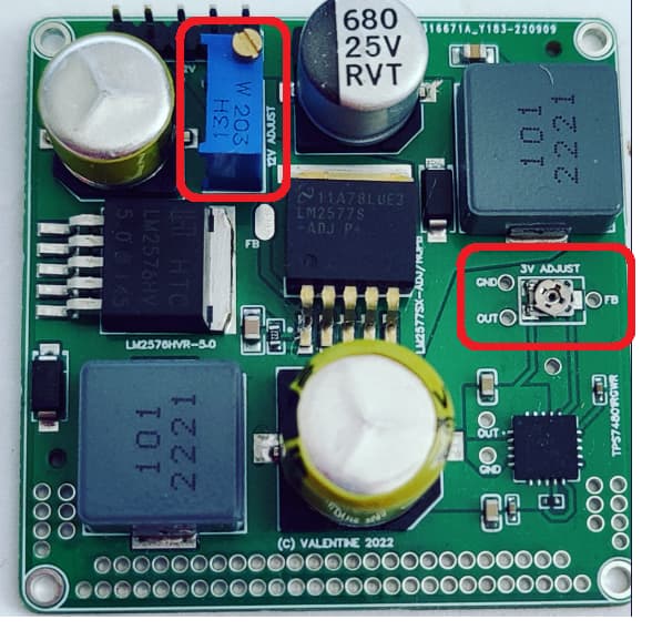
Your approach is correct. There is nothing lazy. People do this all the time and it’s a common practice if you have the time and money to design multiple development revision boards. I keep saying this, but the first Apple iPhone PCB went through thousands of revisions (of course they also had tons of money to throw at the problem). Here are couple different examples from two of my boards:
Please notice the variable resistors. I was not quite sure of the exact values to get certain combined resistance so I added instead two variable resistor dividers, which can be changed with a screwdriver. Also, I added test points to make sure I get the right values (all the holes and the plated lead) Once I got the values, I redesigned the board and added the permanent resistors. Of course this is expensive as it requires time, multiple revisions and manufacturing of the boards ($$$) which you will eventually throw away. Sometimes simulating / calculating a board, especially when it comes to temperature and RFI analysis is complex and it’s easier to just burn a few boards to find the problems. Please always wear goggles and conduct safe experiments in a properly controlled environment. Protect your eyes, face and hands.
Be ready for multiple revisions, burned out boards, smoke and heat. Also make sure you got the money and time to support it. Time is not cheap.
That’s great, please post your designs here. we are always eager to learn from others. Also please ask questions, and perhaps patiently wait a little, for others to get some time to read your questions and answer.
You are not the only one, I also believe there is potential for the FOC stepper driver.
Im wondering if you have gate resistors in your design. I found this recommended from a TI staff:
One of TI experts recommended that I change my mosfets to 60 V. I changed my mosfet and problem removed. And also he recommend me to use gate resistors only at high side no larger than 20 Ω
Ω. And also extend the dead time but dead time is already at its highest value which is 800ns