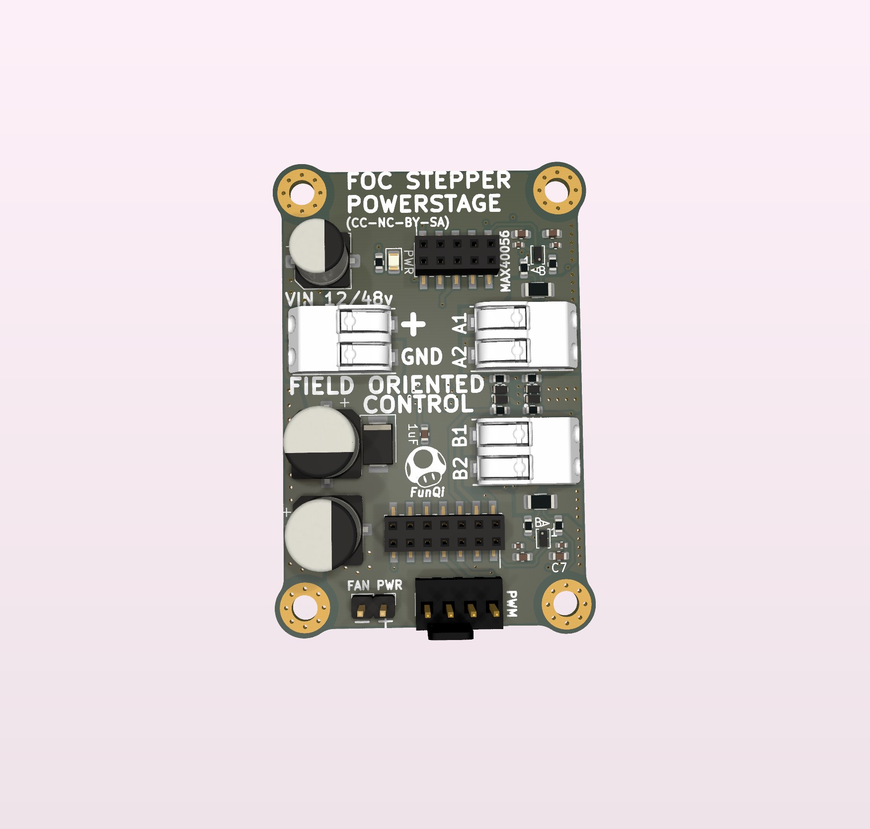
Now that the driver has been integrated into the “MCU-Stack”, the NEMA23 POWERSTAGE is much cleaner. The high side power trace for the FETs is now a almost uninterrupted plane. Furthermore, since there is no need for 12v wires for switching, because of the onboard buck converter, there is suddenly room for a extra electrolytic-capacitor, possibly two (one large per “phase” and a smaller one just because). Getting close…
Also, now that the external FET drivers are out off the way, there is better room for low side current limiting resistor and diode in front of the FETs.
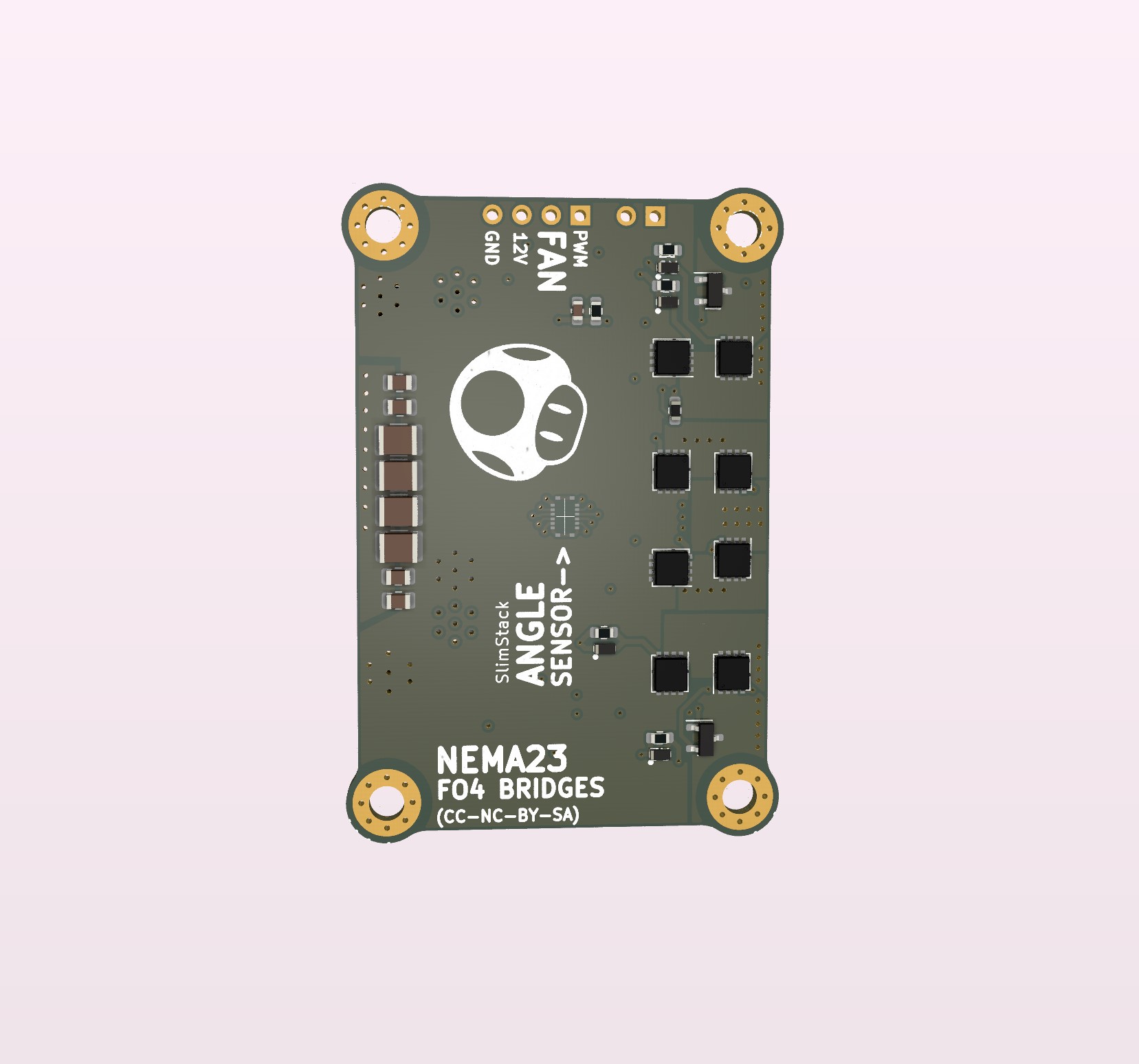
Because there are various power voltages for cooling fans 5v / 12v / 24v I have decided to break out the fan power. The fan header/connector is still relevant because of the PWM speed control, which will adjust the cooling compared to measured heat/temperature development. If using a 5v cooling fan, it could be powered by the 5v USB power. It would then need jumpers from the USB headers to the fan PWR. I will try to break out the regulated 12v for testing on the fan while switching. A Noctua 60mm fan only uses like 0.1amp so in theory it will not drain the power too much. One concern, doing this, is if the 12v fans can handle the 15v the STSpin32G4 buck can output. Raising the switching voltage to 15v could lower the Rds(on) and thereby run the FETs cooler (if the gate can handle 15v).
I am tempted to run the 5V to the cooling fan and make it a closed solder bridge, in order for it to be possible to use 12v, but the 5v would be standard. @runger Du you think it will work, if the CAL_EN pin for the MT6835 was tied to a switch/button ? Hopefully the calibration is a onetime thing and the motor does not need to be mounted to perform it. Its actually a bit difficult to discern, by reading the datasheet, if the CAL_EN shall be toggled or held down?