Delays are only in test sketch.
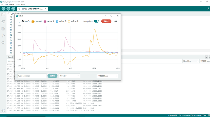
The video shows pulsating operation. Every few seconds I increase the speed, T0.1->T0.5->T1->T2->T3 the power supply switches off. You can feel it best if you block the rotor with your hand. The torque is high but not constant. At higher speeds the engine starts jumping cyclically. As if it were braking? It looks like some impulse is missing or is at the wrong moment.
#include <SimpleFOC.h>
//define motor
#define POLEPAIR 3
//define hall pins
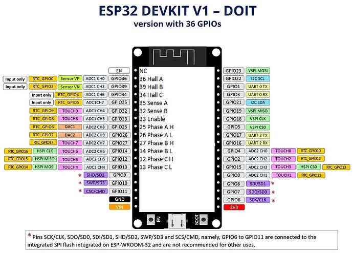
#define HALL_A 36
#define HALL_B 39
#define HALL_C 34
//define driver pins
#define PHASE_A_H 25
#define PHASE_A_L 26
#define PHASE_B_H 27
#define PHASE_B_L 14
#define PHASE_C_H 12
#define PHASE_C_L 13
#define ENABLE_DRV 33
#define SENSE_A 35
#define SENSE_B 32
// BLDC motor instance BLDCMotor(polepairs, (R), (KV), (L))
BLDCMotor motor = BLDCMotor(POLEPAIR);
// BLDC driver instance BLDCDriver6PWM(phA_h, phA_l, phB_h, phB_l, phC_h, phC_l, (en))
BLDCDriver6PWM driver = BLDCDriver6PWM(PHASE_A_H, PHASE_A_L, PHASE_B_H, PHASE_B_L, PHASE_C_H, PHASE_C_L, ENABLE_DRV);
// inline current sense instance InlineCurrentSense(mVpA, phA, phB, (phC))
InlineCurrentSense currentsense = InlineCurrentSense(13.3f, SENSE_A, SENSE_B);
// position / angle sensor instance HallSensor(hallA, hallB , hallC , pole pairs)
HallSensor sensor = HallSensor(HALL_A, HALL_B, HALL_C, POLEPAIR);
void doA(){sensor.handleA();}
void doB(){sensor.handleB();}
void doC(){sensor.handleC();}
float target = 0;
Commander command = Commander(Serial);
void doTarget(char* cmd){ command.scalar(&target, cmd); }
void onMotor(char* cmd){ command.motor(&motor,cmd); }
/////////////////////////// SETUP /////////////////////
void setup() {
// start serial
Serial.begin(115200);
SimpleFOCDebug::enable(&Serial);
// USE_EXTERN is default (1k - 5k recommended), change to USE_INTERN if needed
sensor.pullup = Pullup::USE_EXTERN;
// initialize sensor
sensor.init();
// enable Hall effect interrupts
sensor.enableInterrupts(doA, doB, doC);
// link sensor to motor
motor.linkSensor(&sensor);
// driver config
// power supply voltage [V]
driver.voltage_power_supply = 12; // power supply voltage [V]
driver.voltage_limit = 12; // Max DC voltage allowed - default voltage_power_supply
driver.pwm_frequency = 22500; // pwm frequency to be used [Hz]
driver.dead_zone = 0.01; // dead_zone [0,1] - default 0.02 - 2%
// initialize driver
driver.init();
// link driver to motor
motor.linkDriver(&driver);
// link driver to current sense
currentsense.linkDriver(&driver);
//motor.phase_resistance = 0.3; // [Ohm]
//motor.current_limit = 1; // [Amps] - if phase resistance defined
motor.voltage_limit = 12; // [V] - if phase resistance not defined
motor.voltage_sensor_align = 0.1f;
motor.velocity_limit = 300; // [rad/s] 5 rad/s cca 50rpm
///////////////////////////////// CONTROL //////////////////////////////
motor.controller = MotionControlType::torque; // set motion control type to torque (default)
//motor.controller = MotionControlType::velocity; // set motion control type to velocity
//motor.controller = MotionControlType::angle; // set motion control type to angle / position
//motor.controller = MotionControlType::velocity_openloop; // set motion control type to velocity openloop
//motor.controller = MotionControlType::angle_openloop; // set motion control type to angle / postion openloop
///////////////////////////////// TORQUE //////////////////////////////
motor.torque_controller = TorqueControlType::voltage; // set torque control type to voltage (default)
//motor.torque_controller = TorqueControlType::dc_current; // set torque control type to DC current
//motor.torque_controller = TorqueControlType::foc_current; // set torque control type to FOC current
///////////////////////////////// MODULATION //////////////////////////////
//motor.foc_modulation = FOCModulationType::SinePWM; // set FOC modulation type to sinusoidal (default)
motor.foc_modulation = FOCModulationType::Trapezoid_120; // set FOC modulation type to trapezoidal 120
//motor.foc_modulation = FOCModulationType::SpaceVectorPWM; // set FOC modulation type to space vector modulation
// controller configuration based on the control type
motor.PID_velocity.P = 0.2;
motor.PID_velocity.I = 20;
motor.PID_velocity.D = 0.001;
// velocity low pass filtering time constant
motor.LPF_velocity.Tf = 0.01;
// angle loop controller
motor.P_angle.P = 20;
// Q axis
// PID parameters - default
motor.PID_current_q.P = 1; // 3 - Arduino UNO/MEGA
motor.PID_current_q.I = 0; // 300 - Arduino UNO/MEGA
motor.PID_current_q.D = 0;
motor.PID_current_q.limit = motor.voltage_limit;
//motor.PID_current_q.ramp = 1e6; // 1000 - Arduino UNO/MEGA
// Low pass filtering - default
motor.LPF_current_q.Tf= 0.5; // 0.01 - Arduino UNO/MEGA
// D axis
// PID parameters - default
motor.PID_current_d.P = 1; // 3 - Arduino UNO/MEGA
motor.PID_current_d.I = 0; // 300 - Arduino UNO/MEGA
motor.PID_current_d.D = 0;
motor.PID_current_d.limit = motor.voltage_limit;
//motor.PID_current_d.ramp = 1e6; // 1000 - Arduino UNO/MEGA
// Low pass filtering - default
motor.LPF_current_d.Tf= 0.5; // 0.01 - Arduino UNO/MEGA
// use monitoring
motor.useMonitoring(Serial);
//display variables
motor.monitor_variables = _MON_TARGET | _MON_VOLT_Q | _MON_VOLT_D | _MON_CURR_Q | _MON_CURR_D | _MON_VEL | _MON_ANGLE; // default _MON_TARGET | _MON_VOLT_Q | _MON_VEL | _MON_ANGLE
// downsampling
motor.monitor_downsample = 10000; // default 10
// initialize motor
motor.init();
currentsense.init();
motor.linkCurrentSense(¤tsense);
// for SimpleFOCShield v2.01/v2.0.2
//currentsense.gain_a *= 0.1;
//currentsense.gain_b *= 0.1;
// add command to commander
command.add('T', doTarget, "target");
// command.add('P', onTarget, "target");
command.add('M',onMotor,"motion");
// align sensor and start FOC
motor.initFOC();
_delay(1000);
}
void loop() {
// main FOC algorithm function, the higher the execution frequency, the better, don't put delays in the loop
motor.loopFOC();
// this function can be run at much lower frequency than loopFOC()
motor.move(target);
// significantly slowing the execution down
motor.monitor();
command.run();
}
Its looks correct?? Motor hold by T0 command
And MOT: PP check: fail 99/100 trys
17:32:01.128 -> MOT: Align sensor.
17:32:03.292 -> MOT: sensor_direction==CW
17:32:03.324 -> MOT: PP check: fail - estimated pp: 3.60
17:32:04.052 -> MOT: Zero elec. angle: 0.00
17:32:04.237 -> MOT: Align current sense.
17:32:05.336 -> CS: Switch A-B
17:32:05.336 -> CS: Inv A
17:32:06.412 -> CS: Switch B-(C)NC
17:32:06.452 -> MOT: Success: 4
17:32:06.452 -> MOT: Ready.

