can anyone help me with a schematic of how to connect stm32g431 and drv8305 ive seen the datasheet of drv8305 and it ha a set of pwmhigh and pwmlow pins going to the mcu and i dont if i can just connect them to random i/o of the stm32g431 or should i connect them in to specific pins can somebody help
Timer 1 is used for motor control. Download the datasheet for the particular STM32 you’re using and scroll down to the pinout section where it lists all the pin functions. Look for TIM1CH1, TIM1CH1N … TIM1CH3N. Sometimes more than one pin can be used for the same thing, in which case you can use either one. Connect the TIM1CHx pins to the pwmhigh pins on the driver, and TIM1CHxN to the pwmlow pins. Then pass whatever pins you chose to the BLDCDriver6PWM constructor (it takes the pin names like PA1, PA2, PB1, etc.).
After searching for controller boards and drivers for the past week I’ve came to know that straight out designing a board would be hard and a waste of money if something messes up so I’ve decided to buy a
B-G431B-ESC1 board to first test out the foc functions of my motor will the board be suffice to test a flycat 5010 360kv motor operating at 12v and has 0.5 phase resistance?
Yes, it will work, but be careful with this little ESC - keep voltage low in first tests, and use a power supply with current limit, if possible.
This driver is a bit sensitive and many people have burned theirs…
Also i came across a STSPIN32F0 which has a motor driver within it have you ever tried it ?? can you think we can run on it??? @runger
No, the models of the STSPIN like STSPINF0 don’t have enough flash to really support Arduino framework and SimpleFOC. But the STSPING4 does ![]()
Thanks for the info and also do i need to configure the SimpleFOC library to make it work with STSPING4 or somebody else has already done it ??
Yes, it’s very nice. Build in buck converter. Safety stuff. Of course it does have limitations.
I made this modular approach a while ago. If you see use for that format, let me know. I do need to correct some minor bugs…
@Juan-Antonio_Soren_E do you know reference project on that??? if you know can you share me their links so that i could learn from them. i have some lying around and i like to develop a open source FOC bldc controller using that any help would be appreciated.
You should definitely use the datasheet. If you start from scratch, that’s the way to go. It’s a deep dive into silicon engineering. It is splendid. The support for the MCU/buck/driver is in the lib.
the board looks really cool and compact @Juan-Antonio_Soren_E i’m planning on building the BLDC controller board for using simple FOC with external mosfet attached and i will share the project files hope you help me build it ans also can you recommend me a mosfet for it 'm using a flycat 5010 360 kv motor with a phase resistance of 0.5 ohms and and i want it to handle as much as torques as possible without melting the coil or burning the mosfet what would you recommend ?
Do you mean some special package ? Have you found the one.
no i meant i gonna add mosfet to the stspin32g sorry ![]() can you recommend a mosfet fo the mcu??? i’m pretty much all set just need to figure out the mosfet
can you recommend a mosfet fo the mcu??? i’m pretty much all set just need to figure out the mosfet
Hmm ![]() there are so many, also different prices. Search and you shall find.
there are so many, also different prices. Search and you shall find.
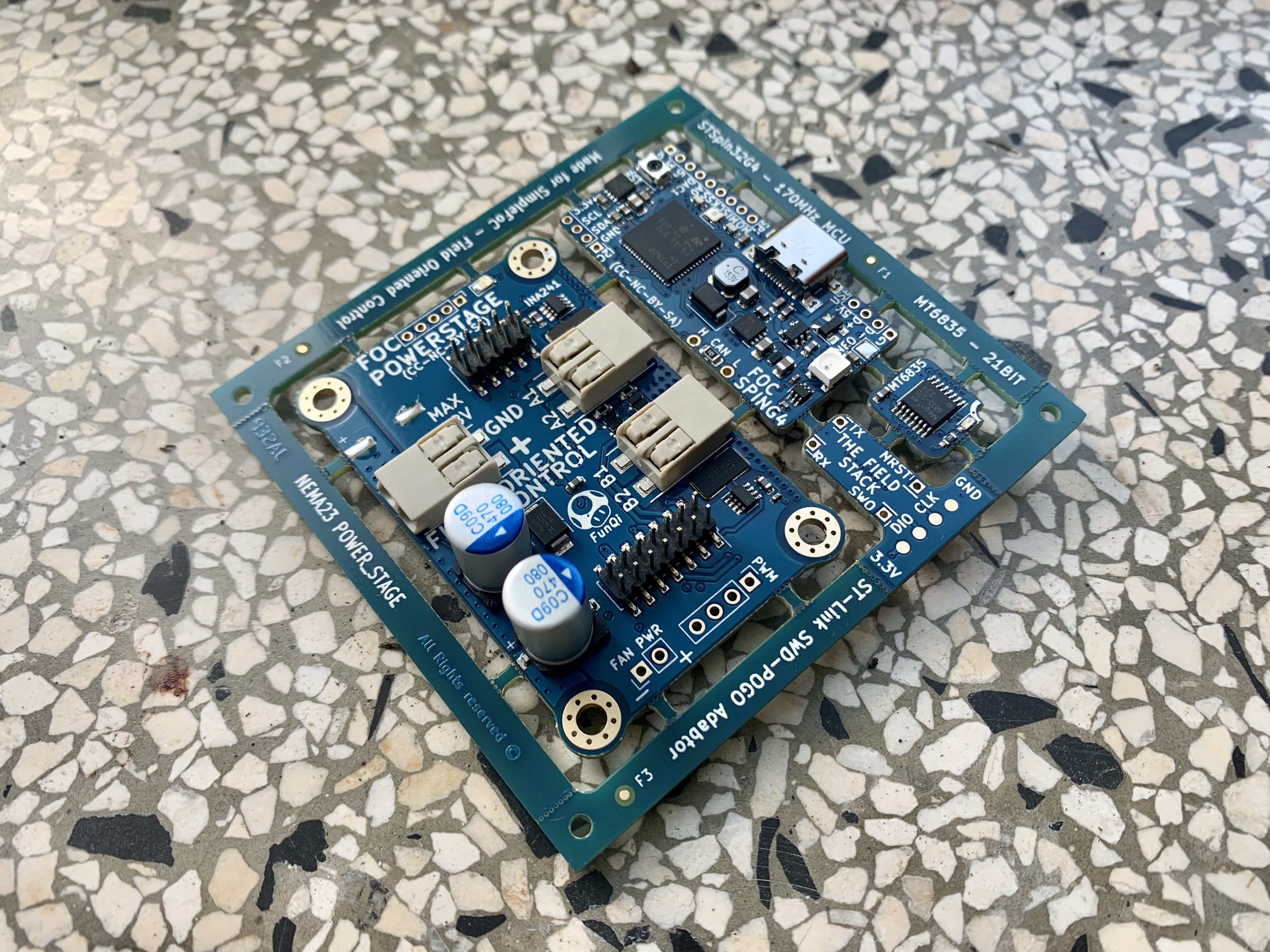
So i decided to build this. i’m gonna integrate the mosfet in a single board for a Bldc controller any heads up? @runger
I had the board working well, I feel, but I never stress-tested it. I stuck to fairly low currents and was using an easy to drive gimbal motor.
I believe @Juan-Antonio_Soren_E was running more current through it, powering LEDs.
So I’d say the board works in principle, but you may still find some bugs when you do your own testing.
If you stick to the same pins and connections then you can easily use the firmware I wrote for it as a starting point for your own - this will save you a lot of time, I think. ![]()
Personally I would change the connectors a bit:
- to include a standard ARM-14 header to connect a ST-Link Mini V3 directly, there’s nothing more convenient for programming/debugging.
- I don’t like the push connectors used for power and phase wires. They’re designed for solid core wire, but I typically use braided wire in my projects, and you can’t force that into those connectors. So I’d definately change those for screw terminals or just solder pads, but of course this is a matter of taste.
- if you’re just running BLDCs you don’t need the 4th phase, so I’d leave that off the design.
One thing to remember is to tie the external LDO, if using such, for 3.3v to a IO pin of the MCU in order to boot that one after the MCU has woken. It is in the datasheet. Something about boot sequence.