STM32F103RCT6 + MP6540H (simple example)

Hi all!
I use a combination of STM32F103RCT6 + MP6540H, but even the simplest example (spinning at a given speed) does not work.

My code for Arduino

 #include <SimpleFOC.h>
 

/* Переменные */
#define UART_TX PA9
#define UART_RX PA10

float target_velocity = 1;

/* BLDCMotor(Pole Pair Number) */
BLDCMotor motor = BLDCMotor(11);
/* BLDCDriver3PWM(PWM_A, PWM_B, PWM_C, Enable_A, Enable_B, Enable_C) */
BLDCDriver3PWM driver = BLDCDriver3PWM(PA6, PA7, PB0, PA5, PA4, PA3);

void setup() {

  /* Инициализация UART */
  do {
    delay(500);
    Serial.setTx(UART_TX);
    Serial.setRx(UART_RX);
    Serial.begin(115200);
  } while (!Serial);
  Serial.println("UART Init Success!");

  /* Настройка драйвера */
  driver.voltage_power_supply = 12;
  driver.voltage_limit = 6;
  driver.pwm_frequency = 25000;
  driver.init();
  motor.linkDriver(&driver);

  motor.voltage_limit = 6;
  motor.velocity_limit = 5; // [rad/s] 50rpm
  motor.controller = MotionControlType::velocity_openloop;
  motor.init();

  Serial.println("Motor ready!");
  _delay(1000);
}

void loop() {
  motor.move(target_velocity);
}

Help with a working example, what am I doing wrong?

Logic analyzer


The PWM signal is only available on phase B and C

In phase A there is only a high level.
All Enable outputs are also at a constantly high level.


Judging by the pins, I did everything right.

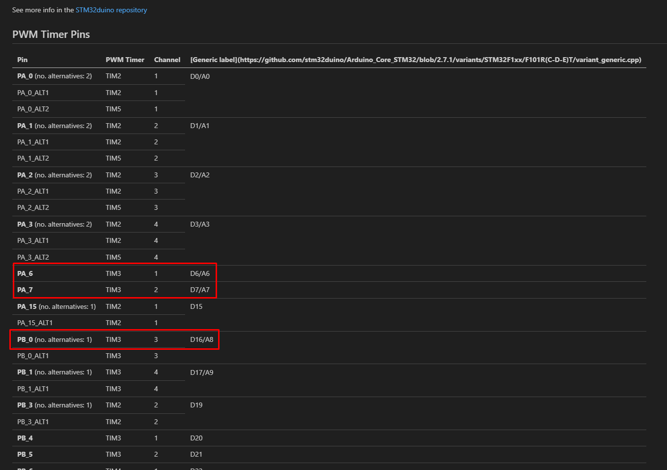
From your pin choice - I guess you are targetting TIM3. Which I guess is ok - it can’t do 6PWM but should be fine for 3PWM.

Perhaps you can enable the printTimerCombination by defining SIMPLEFOC_STM32_DEBUG as a build arg. This should confirm that PA6, PA7 and PB0 have been correctly identified as TIM1 CH1, CH2, CH3 (non inverted)

I suspect this is unrelated but noticed that BLDCDriver3PWM doesn’t set pinMode=OUTPUT on the enable pins - this is left for you to do. But you said you saw HIGH on those enables.

With only 2 PWM working - your motor should be vibrating (not rotating) - if it is not vibrating then you probably have a driver issue as well as a PWM issue.

I take it PWM is missing on PA6, right?

Maybe because there are pullup resistors on all EN-pins?

@POE your code seems incomplete to me. You don’t init FOC. Can’t you use one of the openloop examples and modify them to your MCU?

I think so too.
Try adding motor.loopFOC() in your loop(). This is the function that updates the set voltage to the motors.

BTW. I am happy to see that you’ve found these docs useful!
I am not sure why the link in Generic label did not show properly, are you building the pinout docs locally or you’re using the website: https://docs.simplefoc.com/stm32pinouts/STM32F1xx/F103R(C-D-E)T/pinouts

EDIT: loopFOC actually does not set the voltages in the open loop mode. I was wrong. :slight_smile:
If using open loop, you can use only motor.move().

Very useful work! I ran it locally. But now I’ll go through the website, it’s more convenient)

The pins EN are pulled into the GND through 39k resistors.

My complete scheme

I changed the microcontroller.
The engine jerks under Trapezoid control.
When controlled by Sine, nothing happens.
I suspect that the Enable signals still need to be controlled, but they are constantly at a high level.
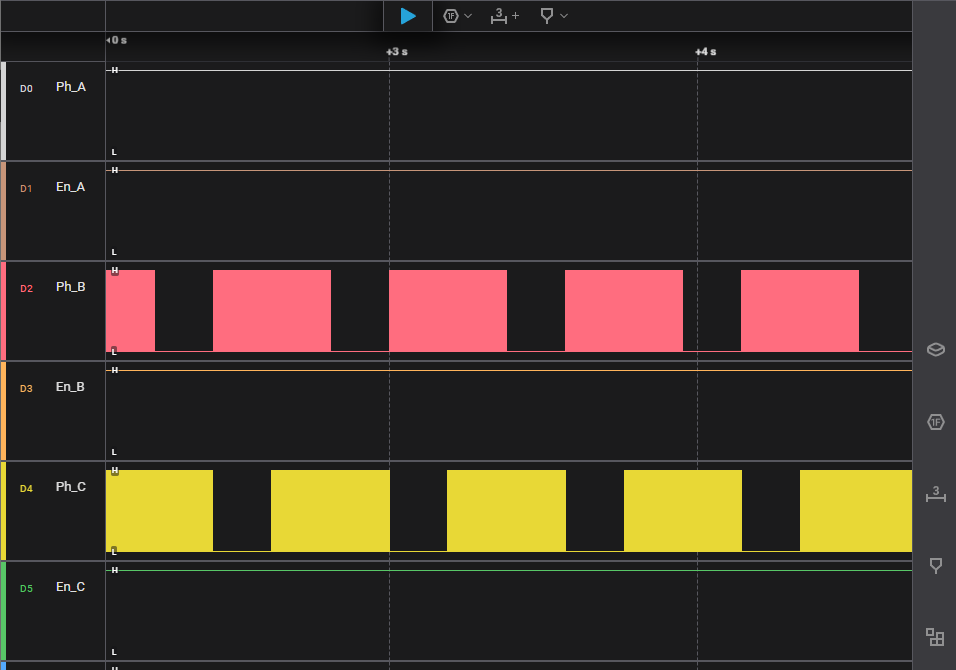
On Monday I can take measurements with a logic analyzer.


The motor began to twitch in Trapezoid mode.
In Sine mode nothing happens.
It is necessary to somehow additionally control the Enable pins on the driver.
At the PWM_A, PWM_B and PWM_C inputs I see a normal PWM signal. But at the driver output I have a signal only in Trapezoid mode.
What could be the problem?
Maybe the library does not work correctly with the MP6540H driver?

No, the MP6540H is just a 3-PWM driver, the library can certainly work with it.

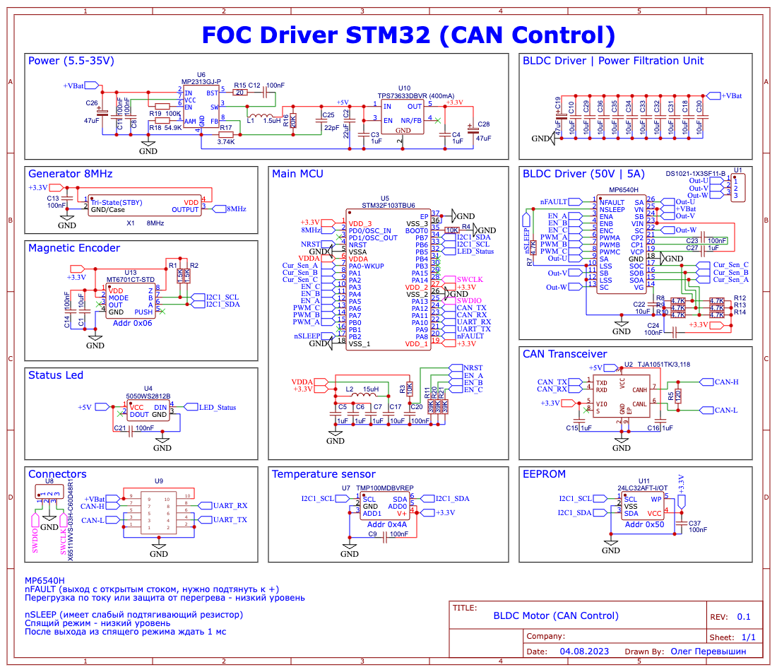
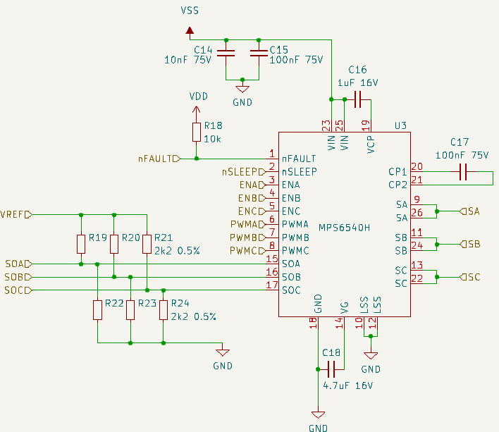
It doesn’t look like you’re dealing with the nSLEEP pin in your code? If your schematic is accurate it looks like you’ll have to pull that high to switch on the driver…

Bringing up a new MCU board with onboard driver needs careful attention to the software side. Don’t assume anything is automatic. Set all the pins to the state you need, make sure the clock setup matches the oscillators you’re actually using, etc…

There is a suspicion that the wrong drivers were received… Instead of MP6540H I got MP6540HA (6PWM). And my circuit is not working correctly.
I’m designing a new board.
I use the Cube to correctly set the pins for connection.
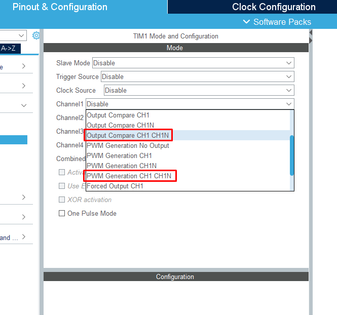
How to choose the right timers when setting up a project?

This driver can also work, I’ve used it myself. You will need 6-PWM mode, and it is a good idea to choose all the pins on TIM1 or TIM8, using “PWM Generation CHx CHxN”. You don’t need the Output Compare option.

Can you show your circuit diagram?
Doesn’t work for me, maybe there’s an error in the circuit…

Sure, but there is nothing special here:

This setup has worked for small motors, although I would not say I stress tested it very much yet.
Power input with bulk capacitance:

Thank you!
At the moment my engine spins for 2-5 seconds and stops. PWM signals are sent to the driver and nFAULT is in a high state (no error).

How do you work with current sensors?
What is your basis for VREF?
And where are ENA, ENB, ENC, PWMA, PWMB, PWMC connected?
Maybe you can show the full diagram?

Sure, this is the full circuit diagram - it is for 2 motors, that’s why I posted only the relevant parts at first:

You can also find the KiCad files here, it’s open source: