Hey @zjor,
Thanks a lot for the time you have put into this, I really appreciate it!
So I have few remarks regarding these l298n based drivers. I have one that is really cheap and it has basically two enable (EN1, EN2) pins and 2 direction (INA1,INB1, INA2, INB2) pins for each pair of h-bridges.
I have seen many times on-line that people just connect digital pins to direciton pins (INx1/2) and put PWM to the enable pin. As in the case of your board, you have hardware inverted direction pins so it is clearly meant for this approach. This would be great for this library, because one arduino would be able to run 3 stepper motors with 2x3 pwm pins.
The other approach is to use enable pins as enable pins really and put pwm on each one of the direction pins. Which means that arduino uno can only driver one stepper motor (it has only 6 pwm and it need 4 for one motor)
4PWM mode works well with l298n based drivers, that is something that many people has already tested 
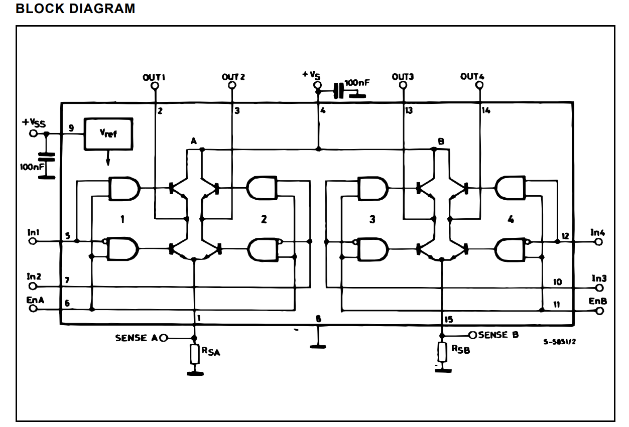
Now 2PWM mode, I was not able to get working. I was really not sure why, until I read the datasheet. Here is the image of the driver circuit:
If you look closely on the diagram, you will see that the enable pins EnA and EnB (EN1 and EN2) are connected to the AND blocks on both h-bridges of one phase. And what is more important they are connected to the AND blocks directly, they are not inverted for lower or higher pair of transistors. This basically means, if you put EnA to zero, both your outputs OUT1 and OUT2 will be floating.
You can see that In1 and In2 have been inverted for lower pair of transistors. So when In1 is HIGH the high transistor passes current, when it is LOW, lower transistor conducts. But if the enable EnA is LOW neither of the transistor pairs 1 and 2 does passes current. The motor thinks it is disconnected.
This basically means that L298N was intended to be driven by putting PWM on In1, In2, In3 and In4 not the enable EnA, EnB.
Now, for DC motors, I guess it doesn’t matter that much, even though it should. I am really not sure how it works at all.
Maybe the transistors still pass some current even if they are not enabled because the motor current does not have anywhere else to go. I am not sure, maybe there are people with more experience here who can help us with this. 
So for fine controlled Stepper motor it is much more complicated than for the DC motor, and this might be the issue that you are seeing. And that might be the reason why you needed one millisecond delay in order to make the rotation smooth. Since motor does not have proper grounding, only when the enable pin is high ( so some part of the duty cycle ) it might have some strange current waveform and it takes a bit longer to stabilize. I am not sure.
Possible work-arround
So, since you have no way to use all 4 pwm pins separately you cannot use the StepperMotor4PWM class which would not have this problem, we could try a different approach. Let’s try putting the PWM on the direction pins!
We will use enable as an enable (so always HIGH) but control the motor with one PWM pins connected to the direction pins. We will still need 2 pwm pins but the logic that is a bit different.
I’ve checked the schematic of your board and the circuit that is inverting the direction pin should be able to support the high-frequency pwm signals, exciting!
In that case we would have bipolar pwm signal in between positive and negative power supply on the motor. Which means that the 0 volts would be exactly in the middle of the range so pwm of 127.
At the moment the pwm setting function is unipolar, one h-bridge of each pair is always set to 0 and the other one is alternating with the pwm frequency. This is the code:
setPwm(float Ua, float Ub) {
  float duty_cycle1(0.0),duty_cycle2(0.0);

  // hardware specific writing
  duty_cycle1 = _constrain(abs(Ua)/voltage_power_supply,0.0,1.0);
  duty_cycle2 = _constrain(abs(Ub)/voltage_power_supply,0.0,1.0);

  // phase 1 direction
  digitalWrite(dir1, Ua >= 0 ? LOW : HIGH);
  // phase 2 direction
  digitalWrite(dir2, Ub >= 0 ? LOW : HIGH);

  // write to hardware
  _writeDutyCycle2PWM(duty_cycle1, duty_cycle2, pwm1, pwm2);
For bi-polar code we would need to do this;
setPwm(float Ua, float Ub) {
  float duty_cycle1(0.0),duty_cycle2(0.0);

  // hardware specific writing
  duty_cycle1 = _constrain( Ua/voltage_power_supply + 0.5,0.0,1.0);
  duty_cycle2 = _constrain( Ub/voltage_power_supply + 0.5,0.0,1.0);

  // write to hardware
  _writeDutyCycle2PWM(duty_cycle1, duty_cycle2, dir1, dir2);
What do you think about this approach, would you be in to try?