Hello
I’m having some issues getting my stepper motor working properly.
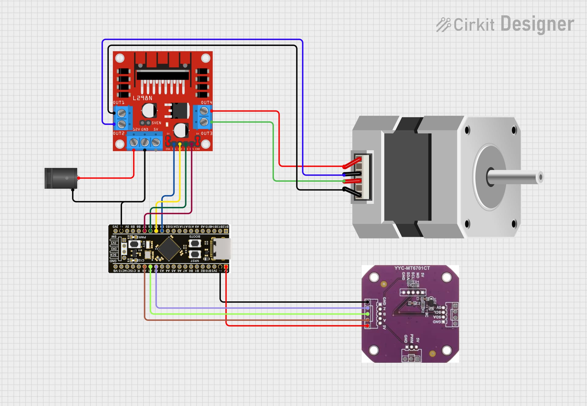
Setup
stepper motor + MT6701 (ABZ) + L298N + STM32F401 black pill
- My encoder test script shows a CPR of 4096.
- It’s a standard 200 pulses/rotation stepper so 50 PP.
- LCR-T4 shows 3 Ω, 4 mH (green-red and blue-black, these values in code don’t help)
Code
#include <SimpleFOC.h>

// Stepper motor instance StepperMotor(polepairs, (R), (KV))
StepperMotor motor = StepperMotor(50);

// Stepper driver instance StepperDriver4PWM(ph1A, ph1B, ph2A, ph2B, (en1), (en2))
StepperDriver4PWM driver = StepperDriver4PWM(PB4, PB5, PB6, PB7);

// position / angle sensor instance Encoder(encA, encB , cpr, (index))
Encoder sensor = Encoder(PA0, PA1, 4096);
void doA(){sensor.handleA();}
void doB(){sensor.handleB();}

// commander instance
Commander command = Commander(Serial);
void doTarget(char* cmd){command.motion(&motor, cmd);}

void setup() {
    // start serial
    Serial.begin(115200);

    // initialize sensor
    sensor.init();
    // enable encoder interrupts
    sensor.enableInterrupts(doA, doB);

    // link sensor to motor
    motor.linkSensor(&sensor);

    // initialize driver
    driver.init();
    // link driver to motor
    motor.linkDriver(&driver);

    // set control loop type to be used
    motor.controller = MotionControlType::angle;

    // controller configuration based on the control type
    motor.PID_velocity.P = 0.2;
    motor.PID_velocity.I = 20;
    motor.PID_velocity.D = 0.001;

    // velocity low pass filtering time constant
    motor.LPF_velocity.Tf = 0.01;

    // angle loop controller
    motor.P_angle.P = 20;

    // set torque control type to voltage (default)
    motor.torque_controller = TorqueControlType::voltage;

    // use monitoring
    motor.useMonitoring(Serial);

    // initialize motor
    motor.init();

    // align sensor and start FOC
    motor.initFOC();

    // add command to commander
    command.add('M', doTarget, "target");

    _delay(1000);
}

void loop() {
    // main FOC algorithm function
    // the faster you run this function the better
    motor.loopFOC();

    // this function can be run at much lower frequency than loopFOC()
    motor.move();

    // significantly slowing the execution down
    motor.monitor();

    // user communication
    command.run();
}
I had some HF vibration issues last time I used a stepper motor, so I added the PID gains.
The problem
When I run the code, I get:
MOT: Align sensor.
MOT: sensor_direction==CW
MOT: PP check: fail - estimated pp: 207.39
MOT: Zero elec. angle: 5.52
MOT: No current sense.
MOT: Ready.
It does something because when I try to turn the motor by hand, it locks it and the current limit of my PSU kicks in.
When I change the polepairs to 200, it ‘works’:
MOT: Align sensor.
MOT: sensor_direction==CCW
MOT: PP check: OK!
MOT: Zero elec. angle: 3.45
MOT: No current sense.
MOT: Ready.
With ‘works’ I mean that the calibration works (even though the calibration move is small, I don’t know if that’s to be expected and can be edited?) and I can move the motor with the commander interface but when I enter M1, it only moves a little over half a turn, and it’s the same for M2, M3, … .
All ideas are welcome.
Thanks
Stijn
