Thank you @Valentine and @runger very much for your swift help, and thanks in advance for any input on the problem I am having below…
I have now been able to run the standalone test and confirm the output of PWM on the pins you recommended (all on the same timer for my board). Amongst many problems, I was using the wrong board group so it flashed the code without an error but didn’t work. The board came as a part of the P-NUCLEO-IHM001 kit.
I am now wrestling with the encoder setup. I have an SSI RLS Orbis Magnetic Encoder and I am using the ‘generic sensor’ setup instructions. However, I am getting some very weird behaviour of the readings when implementing my code into the ‘generic sensor’ script.
This code is needed I believe as the STM32 board does not have SSI functionality and this is the only encoder I can use for our motor (picture of the CAD drawing below for interest). The lead time on an SPI version of this encoder is 6 weeks which is beyond the deadline for our project and I was advised by Reinshaw that is very susceptible to noise.
Here is the code I am using for reading the sensor in a standalone fashion and simply printing a value between 0 and 2 pi and its seems to work well.
int Data = 9;
int NUM = 0;

void setup() {
  // put your setup code here, to run once:
  RCC->AHBENR |= RCC_AHBENR_GPIOCEN;
  GPIOC->MODER = 0x55555555;
  GPIOC->OTYPER = 0x00000000;
  GPIOC->OSPEEDR = 0x55555555;
  //GPIOA->PUPDR = 0x64AAAAAA;
  GPIOC->PUPDR = 0xAAAAAAAA;
  pinMode(Data, INPUT);

  Serial.begin(9600);
}

void loop() {
  // put your main code here, to run repeatedly:
char bits[14];
 GPIOC->BSRR =  0x0000F000;
 for(int i = 0; i < 40; i++){
  delay(0.9);
 }
 for (int t = 0; t < 24; t++){
 //GPIOC->BSRR =  0xF0000000;
 GPIOC->BSRR =  0xF0000F00;
 for(int i = 0; i < 5; i++){
  delay(0.9);
 }
 //GPIOC->BSRR =  0x0000F000;
 GPIOC->BSRR =  0x0F00F000;
 for(int i = 0; i < 5; i++){
  delay(0.9);
 }
 if(digitalRead(Data) == 1 and t<14)
 {
   GPIOC->BSRR =  0x0F00F0F0;
  bits[t]=1;
       // GPIOC->BSRR =  0xFFFF0000;
 }
 else if(t<14)
 {
  //GPIOC->BSRR =  0x0000FFFF;
   GPIOC->BSRR =  0x0FF0F00F;
  bits[t]=0;
        //GPIOA->BSRR =  0x00000F00;
        //GPIOA->BSRR =  0xFFFF0000;
   }
 }
 NUM=0;
   for (int i = 0; i < 14; i++) {
   NUM=NUM+bits[i]*pow(2,(13-i));
  }
  Serial.println(NUM*6.283185/16383, 4);
  Serial.println("\n");
}
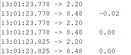
Here is an example output using that code on my STM32 board and turning the encoder quickly by hand
and finally here is the datasheet for that encoder:
Here is my implementation of my code into the generic sensor script;
/**
 *  Generic sensor example code
 * This is a code intended to demonstrate how to implement the generic sensor class
 */
#include <SimpleFOC.h>
int Data = 9;
int NUM = 0;

// sensor reading function example
//  for the magnetic sensor with analog communication
// returning an angle in radians in between 0 and 2PI
float readSensor(){

char bits[14];
 GPIOC->BSRR =  0x0000F000;
 for(int i = 0; i < 40; i++){
  delay(0.9);
 }
 for (int t = 0; t < 24; t++){
 //GPIOC->BSRR =  0xF0000000;
 GPIOC->BSRR =  0xF0000F00;
 for(int i = 0; i < 5; i++){
  delay(0.9);
 }
 //GPIOC->BSRR =  0x0000F000;
 GPIOC->BSRR =  0x0F00F000;
 for(int i = 0; i < 5; i++){
  delay(0.9);
 }
 if(digitalRead(Data) == 1 and t<14)
 {
   GPIOC->BSRR =  0x0F00F0F0;
  bits[t]=1;
       // GPIOC->BSRR =  0xFFFF0000;
 }
 else if(t<14)
 {
  //GPIOC->BSRR =  0x0000FFFF;
   GPIOC->BSRR =  0x0FF0F00F;
  bits[t]=0;
        //GPIOA->BSRR =  0x00000F00;
        //GPIOA->BSRR =  0xFFFF0000;
   }
 }
 NUM=0;
   for (int i = 0; i < 14; i++) {
   NUM=NUM+bits[i]*pow(2,(13-i));
  }
  return (NUM*6.283185/16383);
}

// sensor intialising function // pin assigment
void initSensor(){
  RCC->AHBENR |= RCC_AHBENR_GPIOCEN;
  GPIOC->MODER = 0x55555555;
  GPIOC->OTYPER = 0x00000000;
  GPIOC->OSPEEDR = 0x55555555;
  //GPIOA->PUPDR = 0x64AAAAAA;
  GPIOC->PUPDR = 0xAAAAAAAA;
  pinMode(Data, INPUT);
}

// generic sensor class contructor
// - read sensor callback
// - init sensor callback (optional)
GenericSensor sensor = GenericSensor(readSensor, initSensor);

void setup() {
  // monitoring port
  Serial.begin(9600);

  // if callbacks are not provided in the constructor
  // they can be assigned directly:
  //sensor.readCallback = readSensor;
  //sensor.initCallback = initSensor;

  sensor.init();

  Serial.println("Sensor ready");
  _delay(1000);
}

void loop() {
  // iterative function updating the sensor internal variables
  // it is usually called in motor.loopFOC()
  sensor.update();

  // display the angle and the angular velocity to the terminal
  Serial.print(sensor.getAngle());
  Serial.print("\t");
  Serial.println(sensor.getVelocity());
}
and here is an example of the output;
|13:16:50.365 -> 2.09|0.00|
|13:16:50.365 -> 2.09|0.00|
|13:16:50.419 -> 2.09|0.00|
|13:16:50.419 -> 2.09|0.00|
|13:16:50.419 -> 2.09|0.00|
|13:16:50.419 -> 2.09|0.00|
|13:16:50.465 -> 2.09|0.00|
|13:16:50.465 -> 2.09|0.00|
|13:16:50.465 -> 2.09|0.00|
|13:16:50.465 -> 2.05|-0.73|
|13:16:50.519 -> 2.04|-4.65|
|13:16:50.519 -> 2.03|-5.12|
|13:16:50.519 -> 2.03|-5.87|
|13:16:50.519 -> 1.95|-8.42|
|13:16:50.519 -> 5.77|64.44|
|13:16:50.566 -> 5.68|-61.44|
|13:16:50.566 -> 5.58|-59.88|
|13:16:50.566 -> 5.49|-60.20|
|13:16:50.619 -> 5.39|-58.37|
|13:16:50.619 -> 2.94|-36.83|
|13:16:50.619 -> 2.89|-29.24|
|13:16:50.619 -> 2.85|-29.24|
|13:16:50.666 -> 2.80|-29.01|
|13:16:50.666 -> 2.76|-29.60|
|13:16:50.666 -> 2.36|-29.16|
|13:16:50.666 -> 1.12|-26.02|
|13:16:50.719 -> 1.08|-23.27|
|13:16:50.719 -> 1.05|-22.47|
|13:16:50.719 -> 1.01|-23.24|
|13:16:50.719 -> 0.69|-20.99|
|13:16:50.766 -> -0.10|-16.81|
|13:16:50.766 -> -0.12|-13.12|
|13:16:50.766 -> -0.14|-12.36|
|13:16:50.819 -> -0.16|-11.89|
|13:16:50.819 -> -0.32|-10.25|
|13:16:50.819 -> -0.65|-7.11|
|13:16:50.819 -> -0.66|-5.60|
|13:16:50.866 -> -0.66|-5.10|
|13:16:50.866 -> -0.76|-4.08|
|13:16:50.866 -> -0.77|-2.68|
|13:16:50.919 -> -0.81|-1.08|
|13:16:50.919 -> -0.81|-0.24|
|13:16:50.919 -> -0.81|0.00|
|13:16:50.919 -> -0.81|-0.02|
|13:16:50.966 -> -0.81|0.00|
|13:16:50.966 -> -0.81|0.00|
|13:16:50.966 -> -0.81|0.00|
|13:16:50.966 -> -0.81|0.00|
|13:16:51.019 -> -0.81|0.00|
|13:16:51.019 -> -0.81|0.00|
|13:16:51.019 -> -0.81|0.00|
|13:16:51.019 -> -0.81|0.00|
|13:16:51.066 -> -0.81|0.00|
|13:16:51.066 -> -0.81|0.24|
|13:16:51.066 -> -0.81|0.01|
|13:16:51.066 -> -0.81|0.00|
|13:16:51.119 -> -0.81|0.00|
The issue here is that the position can take on a negative value. It also can continuously count up i.e. that multiple rotations create a number higher than 2pi.
To fix this I have tried various maths modulo operators and creating new variables with various maths libraries but cannot seem to find anything that works. I have also tried performing said operations in various places but the only one that ‘works’ is inside the print operation which will not work for the wider FOC operation of my motor
I was wondering if either of you has any experience with this or know of any fixes.
Many thanks again and sorry for the long post!!! Pictures of motor design from CAD are below. Being machined as I write this. Hope its interesting!