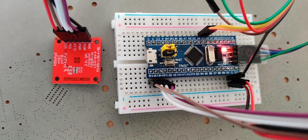
The “SPI” of “Arduino” is not well written. I once encountered various problems like you, so I had to study the underlying protocol of “SPI” communication. Finally, I wrote a code. These codes do not depend on the “SPI” port of the hardware. I simulated the “SPI” port of the hardware with an ordinary “IO” port.
With it, we can easily configure our own “SPI”. I hope it can help you!
//******************************************************************************************************************//
/* Define to prevent recursive inclusion -------------------------------------*/
#ifndef __sw_spi_H
#define __sw_spi_H
#include “stm32f3xx_hal.h”
#ifdef __cplusplus
extern “C” {
#endif
//IO Pin F303RE 左上角,8个位置
#define SPI_SCK_PIN GPIO_PIN_5
#define SPI_SCK_GPIO_PORT GPIOC
#define SPI_MISO_PIN GPIO_PIN_6
#define SPI_MISO_GPIO_PORT GPIOC
#define SPI_MOSI_PIN GPIO_PIN_8
#define SPI_MOSI_GPIO_PORT GPIOC
#define SPI_NSS_PIN GPIO_PIN_9
#define SPI_NSS_GPIO_PORT GPIOC
#define SPI_SCK_GPIO_CLK_ENABLE() __HAL_RCC_GPIOC_CLK_ENABLE()
#define SPI_MISO_GPIO_CLK_ENABLE() __HAL_RCC_GPIOC_CLK_ENABLE()
#define SPI_MOSI_GPIO_CLK_ENABLE() __HAL_RCC_GPIOC_CLK_ENABLE()
#define SPI_NSS_GPIO_CLK_ENABLE() __HAL_RCC_GPIOC_CLK_ENABLE()
#define MOSI_H HAL_GPIO_WritePin(SPI_MOSI_GPIO_PORT, SPI_MOSI_PIN, GPIO_PIN_SET)
#define MOSI_L HAL_GPIO_WritePin(SPI_MOSI_GPIO_PORT, SPI_MOSI_PIN, GPIO_PIN_RESET)
#define SCK_H HAL_GPIO_WritePin(SPI_SCK_GPIO_PORT, SPI_SCK_PIN, GPIO_PIN_SET)
#define SCK_L HAL_GPIO_WritePin(SPI_SCK_GPIO_PORT, SPI_SCK_PIN, GPIO_PIN_RESET)
#define MISO HAL_GPIO_ReadPin(SPI_MISO_GPIO_PORT, SPI_MISO_PIN)
#define NSS_H HAL_GPIO_WritePin(SPI_NSS_GPIO_PORT, SPI_NSS_PIN, GPIO_PIN_SET)
#define NSS_L HAL_GPIO_WritePin(SPI_NSS_GPIO_PORT, SPI_NSS_PIN, GPIO_PIN_RESET)
extern void SWSPI_Init(void);
extern uint16_t AS5048_SPI_ReadWrite(uint16_t data);
extern uint16_t DRV83XX_SPI_ReadWrite(uint16_t data);
extern uint16_t spi_exchange(uint16_t x);
extern uint16_t SWSPI_GetAS5048_Raw(void);
extern uint16_t SWSPI_Drv83xx_Write(uint16_t TxData);
extern uint16_t SWSPI_Drv83XX_readwrite(uint16_t TxData);
#ifdef __cplusplus
}
#endif
#endif /*__sw_spi_H */
//*****************************************************************************************************************//
#include “sw_spi.h”
#include “delay.h”
#ifdef __cplusplus
extern “C” {
#endif
extern void SWSPI_Init(void)
{
/##-1- Enable peripherals and GPIO Clocks #################################/
/* Enable GPIO TX/RX clock */
SPI_SCK_GPIO_CLK_ENABLE();
SPI_MISO_GPIO_CLK_ENABLE();
SPI_MOSI_GPIO_CLK_ENABLE();
SPI_NSS_GPIO_CLK_ENABLE();
/##-2- Configure peripheral GPIO ##########################################/
/* SPI SCK GPIO pin configuration */
GPIO_InitTypeDef GPIO_InitStruct;
GPIO_InitStruct.Pin = SPI_SCK_PIN ;
GPIO_InitStruct.Mode = GPIO_MODE_OUTPUT_PP;
GPIO_InitStruct.Speed = GPIO_SPEED_FREQ_HIGH;
HAL_GPIO_Init(SPI_SCK_GPIO_PORT, &GPIO_InitStruct);
HAL_GPIO_WritePin(SPI_SCK_GPIO_PORT, SPI_SCK_PIN, GPIO_PIN_RESET);
/* SPI MOSI GPIO pin configuration */
GPIO_InitStruct.Pin = SPI_MOSI_PIN;
GPIO_InitStruct.Mode = GPIO_MODE_OUTPUT_PP;
//GPIO_InitStruct.Pull = GPIO_PULLUP;
GPIO_InitStruct.Speed = GPIO_SPEED_FREQ_HIGH;
HAL_GPIO_Init(SPI_MOSI_GPIO_PORT, &GPIO_InitStruct);
HAL_GPIO_WritePin(SPI_MOSI_GPIO_PORT, SPI_MOSI_PIN, GPIO_PIN_SET);
GPIO_InitStruct.Pin = SPI_NSS_PIN;
GPIO_InitStruct.Mode = GPIO_MODE_OUTPUT_PP;
HAL_GPIO_Init(SPI_NSS_GPIO_PORT, &GPIO_InitStruct);
HAL_GPIO_WritePin(SPI_NSS_GPIO_PORT, SPI_NSS_PIN, GPIO_PIN_SET);
/* SPI MISO GPIO pin configuration */
GPIO_InitStruct.Pin = SPI_MISO_PIN;
GPIO_InitStruct.Mode = GPIO_MODE_INPUT;
HAL_GPIO_Init(SPI_MISO_GPIO_PORT, &GPIO_InitStruct);
}
/##################################################################/
/* AS5048A SPI mode == CPOL=0,CPHA=1 */
/*1. Before SPI transmission, SCK should be in the low position; */
/*2. Since the data acquisition occurs at the falling edge, we need /
/ to simulate the falling edge and carry out bidirectional data /
/ transmission after the falling edge begins */
/*3. Drv8301, 8305 and 8323 are the same SPI mode */
/4. A complete SPI process of transmitting 16bit needs about /
/ 16 * 60 = 960 (NOP). For the convenience of estimation, 960 /
/ “NOPs” are calculated as 1000 “NOPs”, and each NOP of 72m MCU /
/ is about 13.89ns, so the time of one SPI is 14uS. /
/##################################################################/
extern uint16_t DRV83XX_SPI_ReadWrite(uint16_t data)
{
uint16_t xx, dt, dts;
dt = 0;
dts = data;
for (xx=0; xx<16; xx++)
{
SCK_H;
HAL_GPIO_WritePin(SPI_MOSI_GPIO_PORT, SPI_MOSI_PIN, dts >> 15);
dts<<=1;
for (volatile int k = 0;k <55;k++) {__NOP();}
SCK_L;
dt<<=1;
dt|= MISO;
for (volatile int k = 0;k <55;k++) {__NOP();}
}
if(HAL_GPIO_ReadPin(SPI_SCK_GPIO_PORT, SPI_SCK_PIN)==1) {SCK_L;}
return dt;
}
extern uint16_t AS5048_SPI_ReadWrite(uint16_t data)
{
uint16_t xx, dt, dts;
dt = 0;
dts = data;
for (xx=0; xx<16; xx++)
{
SCK_H;
for (volatile int k = 0;k <30;k++) {__NOP();}
SCK_L;
HAL_GPIO_WritePin(SPI_MOSI_GPIO_PORT, SPI_MOSI_PIN, dts >> 15);
dts<<=1;
dt<<=1;
dt|= MISO;

for (volatile int k = 0;k <25;k++) {__NOP();}
}
return dt;
}
extern uint16_t spi_exchange(uint16_t x) {
uint16_t rx;
rx = DRV83XX_SPI_ReadWrite(x);
return rx;
}
extern uint16_t SWSPI_GetAS5048_Raw(void){
uint16_t DeRxBuffer,DeTxBuffer;
DeTxBuffer = 0b0100000000000000 |0x3fff;
NSS_L;
for (volatile int k = 0;k <75;k++) {__NOP();} //delay_us(2);
AS5048_SPI_ReadWrite(DeTxBuffer);
for (volatile int k = 0;k <75;k++) {__NOP();} //delay_us(2);
NSS_H;
//delay_us(5);
for (volatile int k = 0;k <400;k++) {__NOP();}
DeTxBuffer =0;
NSS_L;
for (volatile int k = 0;k <75;k++) {__NOP();} //delay_us(2);
DeRxBuffer = AS5048_SPI_ReadWrite(DeTxBuffer);
for (volatile int k = 0;k <75;k++) {__NOP();} //delay_us(2);
NSS_H;
return DeRxBuffer & ~0XC000 ;
}
extern uint16_t SWSPI_Drv83xx_Write(uint16_t TxData)
{
uint16_t DeRxBuffer,DeTxBuffer;
DeTxBuffer = TxData;
DeRxBuffer = 0;
NSS_L;
for (volatile int k = 0;k <150;k++) {__NOP();} //delay_us(2);
DeRxBuffer = DRV83XX_SPI_ReadWrite(DeTxBuffer);
for (volatile int k = 0;k <150;k++) {__NOP();} //delay_us(2);
NSS_H;
//delay_us(10);
for (volatile int k = 0;k <720;k++) {__NOP();}
return DeRxBuffer;
}
extern uint16_t SWSPI_Drv83XX_readwrite(uint16_t TxData)
{
uint16_t DeRxBuffer,DeTxBuffer;
DeTxBuffer = TxData;
DeRxBuffer = 0;
NSS_L;
DRV83XX_SPI_ReadWrite(DeTxBuffer);
NSS_H;
//delay_us(10);
for (volatile int k = 0;k <720;k++) {__NOP();}
NSS_L;
DeRxBuffer = DRV83XX_SPI_ReadWrite(DeTxBuffer);
NSS_H;
return DeRxBuffer;
}
#ifdef __cplusplus
}
#endif
//**********************************************************************************************//