I was reading through the theory of FOC and in particular, the space vector PWM section and I noticed that at the end of the BLDCMotor::setPhaseVoltage() function, the timings (Ta, Tb, Tc) are converted into voltages (Ua, Ub, Uc) before being sent to the driver. Doesn’t that defeat the purpose of using space vector modulation? If you just set voltages, how is that any different from the sinePWM? I thought one of the benefits of SVM was that it only switches one phase at any one time, which reduces switching losses but if you leave it up to the driver, you have no control over that.
In the documentation, it is mentioned that using SVM can give slightly higher power because of the “double peak”, allowing the full voltage range to be used. This is from third harmonic injection, which can be implemented in the sinePWM method as well. In fact, with the current SVM implementation, it is actually injecting a triangle wave, not a sine, so it’s not optimal either (but probably good enough).
I understand not every driver allows direct control of the PWM switching and the benefits of having a common interface but if implementing third harmonic injection to the sinePWM function achieves exactly the same thing as SVM, what’s the advantage of having both? Alternatively, the driver interface could be extended to allow setting of timings directly.
Sorry for the late reply. I’m also not the best person to answer this question, but I will make an attempt:
PWM output is always simulating an analog voltage level. The expectation is that the motor, being an inductive load, will smooth this high frequency digital output into a slower analog curve.
the FOC algorithm should ideally execute quickly enough so that there are many iterations of the algorithm for each electrical revolution of the motor. So the result is that the PWM output levels are changed multiple times per commutation step, and wind up approximating an analog waveform, for example sinusoidal, or if you choose SVM the more trapezoidal form.
I’m not knowledgable enough to comment on your points regarding the triangle wave or third harmonic injection. Perhaps someone else has some thoughts on this.
Thank you for your reply! I understand the PWM is simulating an analog voltage but I believe there are many ways to do the switching which can affect the overall performance and efficiency. I am not an expert on motor controllers so I’m just learning as I go.
I actually did a little digging and found more information regarding SVM. It is simply a way to efficiently (computation wise) perform the conversion from the desired voltages to the PWM signals and does the inverse Park/Clarke transforms + PWM timings in one magical step. The way the algorithm works naturally adds the triangle wave, leading to the double peaks. The exact same output can be achieved using the inverse Park/Clarke, then adding the third harmonic wave manually but this would require many more operations and thus execute slower.
The output of SVM are PWM timings and are useful if you are switching the FETs manually but when you have PWM timers on the microcontrollers performing the switching, this is unnecessary and that’s why it’s converted into voltages. Looking through the code, I found that all the PWMs are set to center-aligned, so the actual switching patterns will end up being the same. If you send the output to an external IC that does the PWM switching, then a center-aligned PWM is no longer guaranteed.
The switching also becomes important when current sensing is implemented in the future hopefully. There are optimal windows for sensing, since you need to allow some time for the current to stabilize after a switch to prevent inaccurate readings and with low-side shunts, you can only read it when that phase is active. For this to be implemented, the PWM switching may have to be done manually and a timer interrupt can be set up to take a current reading at the correct times.
The output of the FOC algorithm are the voltages for the 3 phases… the algorithm computes the ideal Q and D currents/voltages and converts them to the 3 phase voltages. These are then converted to PWM levels for the given hardware by the BLDCDriver code.
Ideally, we use centre-aligned PWM, which results in nice signals even when changing target values/load, but this is hardware dependent.
I’m not sure what you mean by “switching FETs manually”? Do you mean when the MCU controls the FETs directly (via simple drivers, or using logic level FETs) as opposed to using a motor control IC with integrated FETs or drivers?
Normally (though this will depend on the exact IC) the motor drivers can handle PWM input up to a certain speed, and either pass it through with a certain small delay, or have their internal strategies for producing the output PWM signals. It gets quite complicated, and you have to dive into the datasheet of the specific IC in question. But generally speaking, the ICs can handle the PWM inputs well, and add protection features like dead-time insertion to prevent “blow through” (short circuits caused by having high and low FETs open at the same time) and over-current protection.
In terms of the current sensing, we currently support inline current sensing (at least on some hardware), and are working on low-side current sensing. For the low-side current sensing it is indeed very important to sync the ADC measurements to the PWM. There are different (hardware-dependent) strategies for doing so, and this is an area of active development in the library right now.
Hi @runger, thanks for taking the time to respond and sorry for the confusion.
When I said manually I meant toggling IOs for the FETs in an interrupt routine rather than just setting the timers to PWM mode and letting it run. What I meant by the PWM timings was actually setting the timer counter target values rather than the desired phase voltages. The SVM gives you the exact times of when to switch the FETs, so I was just wondering if it would be slightly more optimal to use that directly rather than converting it into phase voltages. Of course, in the end the result is the same and setting phase voltages gives you a common interface regardless of what driver or MCU you are using.
Sorry, I didn’t realise the inline sensing was already implemented on some MCUs. It uses a sync in the initialisation so the manual interrupt I was thinking of isn’t necessary. That’s a pretty neat way of doing it. It looks like the sensing is only done when all the low-side FETs are on. If one of the phases is close to 100% duty, would this become a problem as your window gets very small?
Yes, this is a problem, you have to account for it in software. For example, you can throw out the reading from the phase with the lowest duty cycle, and calculate its value from the other two phases.
I see, that makes sense. You can only do that if you have 3 shunts right? How would you do it if you only had 2? If the motor is spinning, it wouldn’t be a huge problem because you’ll only have brief periods when this occurs but if you are trying to hold position, does this mean you must have 3 shunts?
It depends a bit on your exact goals - it is in fact possible to do low side sensing with a single shunt (on the GND path of all 3 phases), but the software has to take into account the current state of the commutation (FETs) and perform more complex calculations. TI has an app-note and sample code for this somewhere, but we don’t currently support it in SimpleFOC.
There are several driver ICs (like the L6234 or the STSPIN233) which are configured for 2-shunt low-side sensing. You basically use Kirchhoff’s laws to work out the 3rd phase, but as you point out there are constraints as to when you can accurately measure.
Otherwise it is typical to use 3 shunts. Generally speaking I think this makes things easier also in the sense that calculated values are less stable than directly measured ones, so using 3 shunts should be more resistant to noise, small errors, etc…
It also depends on the overall goal: if you’re aiming for “sensorless” commutation (which we currently don’t support), then the implication is typically that this only works for a turning motor, and you use open-loop control to start it up. If you want to hold positions, like in a robotics application, then 3-shunts would be the way to go, but normally you will also need a position sensor in this case.
Here is the app-note I was referring to:
TI and ST both have some very cool documentation on motor control.
That’s a really good document, thanks. I basically arrived at the same conclusion that 3 shunts is the best for precise position control which is what I am interested in.
Hey guys,
this is a great discussion, thans for the question @bronsonarnold.
So we definitelly do not have the power on most of the chips that were using at the moment to do an interrupt styled pwm switching (switching manually). Those kinds of approaches are done for big industrial machines with powerful DSP or FPGA boards. And you are right that the SVM was intended for that kind of use, to control the switches directly. I’ve not even tried to implement this on a MCU, it would be interesting to see what is the switching frequency that we can achieve,(for example for stm32 nucleo-64 boards) but I doubt it that we would be able to surpass 5-10kHz.
You do not have the control over it direclty, it is true. But be setting the duty cycles of the driver you are achieving the same waveform as if you would be manipulating the switches manually. So if you look at it from that perspective then you actually do have the control over them.
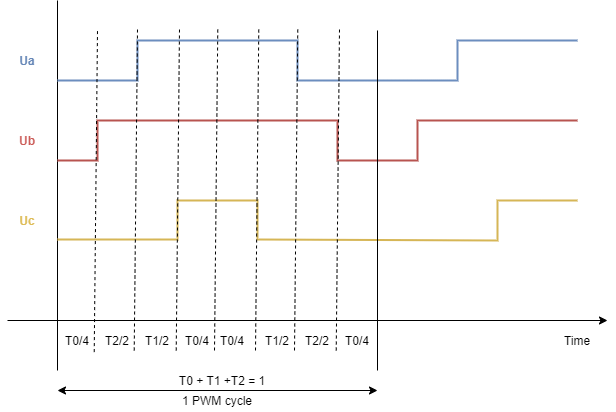
Here is the image from the docs showing one duty cycle of the svm:
You can find a bit more info at:
That is a great question. And you are right, in the current implementation of the simplefoc the only difference in between the two is the waveform and how its calculated. It is true that svm’s waveforms if close to the sine + 3rd harmonic and that could be added as a feature as well to the library. The svm is a bit more triangular and since a lot of BLDCs have more or less triangular currents (not really sine) then this approach uses the DC buss voltage a bit more efficiently.
But you are rigth that without implementing it in the low level (manually switching the mosfets) it is just another waveform at the end. But on the other hand, even if we would implement it in low level, we would still get the same waveform at the output.
As the simplefoc is an educational platform we’ve preferred to have the most simple(one that can be transferred on most of the platforms) solution that demonstrates the principle than the optimal one. And that is something you will find in a lot of choices we’ve taken in the code.
But on the other hand, I’d be very interested to collaborate over topics like this one and improve the current implementations of the algorithms in the library. So, don’t hesitate if you have some suggestions.
Wow, thanks for the super detailed response @Antun_Skuric and sorry for the late reply. That answers all my questions. I really learnt a lot from digging through the code and it’s good to know my understanding wasn’t totally off. The implementation choices made make perfect sense when you weigh the benefits of being able to run on different hardware. I was just curious on whether the points mentioned were valid if you wanted to really optimise for a particular hardware setup. I currently do not have all the hardware required to test with, but I will definitely help out if I ever do.