Hello all! I have designed this board for size critical projects. It features a DRV8711 BLDC driver from Texas Instruments and AS5600 magnetic encoder.
Here is general information:
-28.5mm x 30mm footprint
-Operating voltage: 5-12V
-Continious current: 2A(limited by connectors)
-Current sense feedback(0.5V/A)
-AS5600 12 bit magnetic encoder
Hoping that it will work smoothly with simplefoc! Will update this thread once I have got the boards produced.
You have used a 10V capacitor for the input voltage (C1, C4, C7), when you state the operating voltage will be 5-24V. You need to pick a capacitor rated for at least your operating voltage, otherwise the capacitor might fail (possibly explode). There is also another 6.3V capacitor (C3) which you need to replace for the same reason. I also suggest limiting the maximum operating voltage to 20V, as the absolute maximum rating of the chips should not be interpreted as continuous ratings.
You can’t connect VIN to the 5V pin of U2 (AS5600) unless you only intend to run the board on 5V. You should add a buck regulator or LDO to generate a 5V rail.
You say that the gain setting is 0.5V/A, but you have tied the GAIN pin to AVDD, which means the gain is actually set to 2V/A. You need to connect it to GND via a 47k resistor to get 0.5V/A gain.
You can get rid of R2 if you want the nFAULT pin to light a LED. In your current schematic R2 does nothing.
I would replace this encoder with a fast one. 5600 is for servos.
Also it would be best if you post a picture or pdf of the schematics and pcb layouts. I don’t have kikad. Also downloading gerbers and looking at them is very time taking. You can get a lot more help if you make it easy for people to instantly see your design.
I was about to comment the same, it would be nice if .pdf is provided for schematic and layout, even though I use Kicad, I don’t want to have to setup whole project just to look over
You can get MT6701 encoder, higher resolution, smaller, lower noise, and cheaper than AS5600. Or there are many others to pick, too.
As much as I passionately hate reddit and wish it sinks to the bottom of the whatever hell is on earth, they do have some good advice about PCB reviews that you must follow to get the best help here.
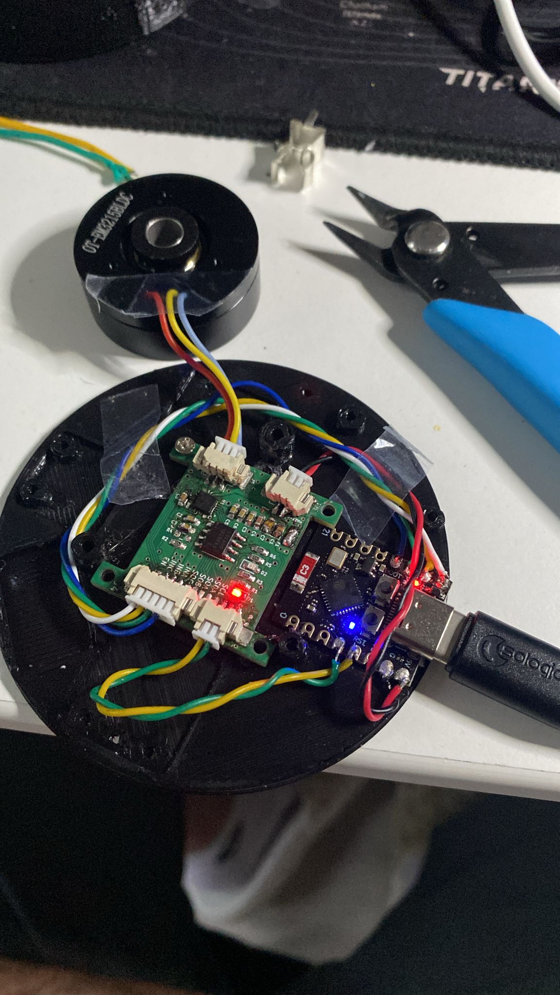
good news is that MT6701 is directly compatible with AS5600, so I was able to make it work with it as well! Currentse sense feedback also improves torque control significantly!
I believe that this solution could be useful for volume/size critical projects which utilizes torque control mode.
I just saw this review, and thank you very much. I have updated schematic accordingly, and in my case since I have been using 5V level, everything was fine luckily!