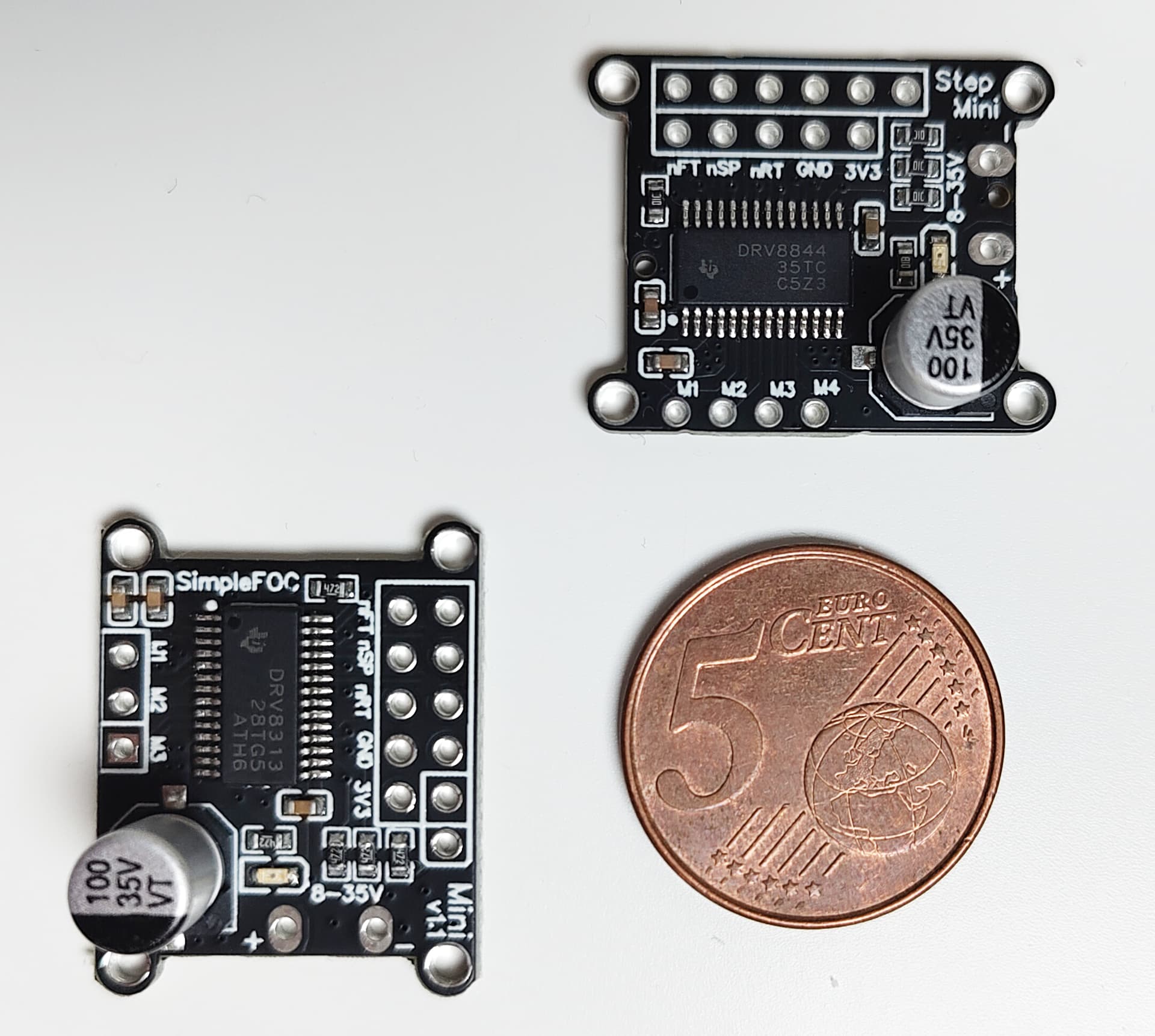
I just waned to let you know that there is a new addition to the SimpleFOCMini family, this time more specific to stepper motors, its called StepMini. This board has the same footprint as the SimpleFOCMini but is based on the DRV8844 driver.
The aim of the project is to provide a simple stepper driver that is compatible with SimpleFOC and to try to replace the outdated L298Ns. Also the aim is to provide a simple project that can be easily forked, modified and customized for your own projects!
I am also working on the new shield for steppers based on the DRV8844 with inline current sensing.
If you guys have some ideas about better driver chips than DRV8844 don’t hesitate to let me know!
Its quite limited in performance, but also very available and easy to work with.
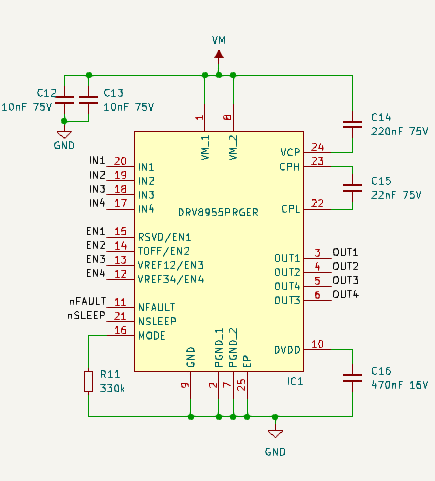
I have a design for steppers kicking around that I have not tested out yet… it’s based on the DRV8955, which looks like it is similar power levels though. Might be worth comparing to the DRV8844…
The small size of DRV8955 would be nice for something I’ve been wanting to do for a long time, making a pin-compatible stepstick for 3D printer motherboards and GRBL boards. Too bad it’s not available on LCSC. But I’ll probably have to solder the driver myself either way, since DRV8844 would have to go on the back due to lack of space. I suppose I’ll try routing it with both and see if the idea is feasible at all. Only 10x20mm available work area between the rows of pins, and I’m going to need an encoder connector and programming/debugging connector which will cut that down to more like 10x14mm…
That’s a really nice idea… I was thinking along the same lines myself
The problem with going so small (as you well know, I guess) is the vias. As a HDI design I think it would not be a problem going down even to 10x14mm, but with through hole vias its a real challenge to fit everything. For me, making HDI boards for hobby purposes for myself is still too expensive.
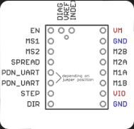
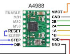
Regarding the programming/debugging connector, it seems there is a certain amount of optionality to the module’s pinout:
Putting the chip on the back has better cooling options. Instead of glueing a heatsink on the plastic housing you can create a GND-pad on top.
But why do you need encoder inputs? Does the DRV chip directly support closed loop?
Is there any board using these (slightly outdated) addon-drivers supporting closed loop?
If so, doesn’t the motherboard provide such connectors?
Reading the DRV8955 datasheet more closely, it is a very cool chip. The VREF pins are used to set a current limit, and instead of shutting down when exceeded like DRV8844, it automatically pulses the mosfets to keep below the limit value. But you do have to give up independent control of hi-z mode on each channel, since the VREF and TOFF pins are shared with the enable pins. If you connect the mode pin to ground with a 330k resistor, the enable pins are usable but the current limiting feature is disabled. As far as I know, trapezoid modulation is the only place SimpleFOC uses independent hi-z, so I think current limiting is more useful. You can still disable all outputs together with the sleep pin.
The TOFF pin sets the pulse width for limiting, but I’m not sure what will be the best value for it. There’s one example where it uses multiple short off pulses to keep the current under control, and another where it uses longer off time to synchronize with the input PWM, effectively limiting the PWM duty. But I don’t think you could get perfect synchronization at high PWM duty since you don’t know whether the limit will trip early or late in the cycle. If it trips early, the off period may end before the cycle is finished so you get another pulse of current. If it trips late, the off period could extend into the next PWM cycle. I don’t suppose it matters much in any case.
// Open loop motor control example
#include <SimpleFOC.h>
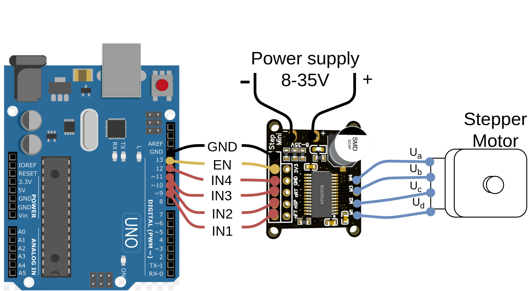
// pins if stacked on the UNO headers from 9 to GND pin
#define IN1 9
#define IN2 10
#define IN3 11
#define IN4 12
#define EN 13
// Stepper motor & driver instance
StepperMotor motor = StepperMotor(50);
StepperDriver4PWM driver = StepperDriver4PWM(IN1, IN2, IN3, IN4, EN);
//target variable
// instantiate the commander
Commander command = Commander(Serial);
void doTarget(char* cmd) { command.scalar(&motor.target, cmd); }
void doLimit(char* cmd) { command.scalar(&motor.voltage_limit, cmd); }
void setup() {
// driver config
// power supply voltage [V]
driver.voltage_power_supply = 12;
// limit the maximal dc voltage the driver can set
// as a protection measure for the low-resistance motors
// this value is fixed on startup
driver.voltage_limit = 6;
driver.init();
// link the motor and the driver
motor.linkDriver(&driver);
// limiting motor movements
// limit the voltage to be set to the motor
// start very low for high resistance motors
// current = voltage / resistance, so try to be well under 1Amp
motor.voltage_limit = 3; // [V]
// open loop control config
motor.controller = MotionControlType::velocity_openloop;
// init motor hardware
motor.init();
// add target command T
command.add('T', doTarget, "target velocity");
command.add('L', doLimit, "voltage limit");
Serial.begin(115200);
Serial.println("Motor ready!");
Serial.println("Set target velocity [rad/s]");
_delay(1000);
}
void loop() {
// doesn't do anything in open-loop
motor.loopFOC();
// open loop velocity movement
// using motor.voltage_limit and motor.velocity_limit
// to turn the motor "backwards", just set a negative target_velocity
motor.move();
// user communication
command.run();
}
Enable is managed within the StepperMotor4PWM class. If you wanna enable the board by hand, it should be set to HIGH.