SimpleFOC Power Shield-D Beta

Hello all!

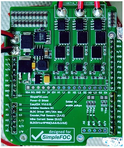
After a while, we are announcing a Beta version of the SimpleFOC PowerShield-D.

D stands for [D]iscrete Power Shield, currently designed to work on Arduino UNO footprint pinout.

The shield is sized for 30A peak power. Features:

  1. Overvoltage / ESD protection
  2. Reverse voltage protection.
  3. Buck converter with chained 5V and 3.3V for powering external components as well as the Arduino shield to form a standalone module.
  4. Discrete drivers and MOSFETs
  5. In-line current hall-based sensors with inherent galvanic isolation.
  6. Pinouts current sensing, and pull-downs for I2C and hall sensors.

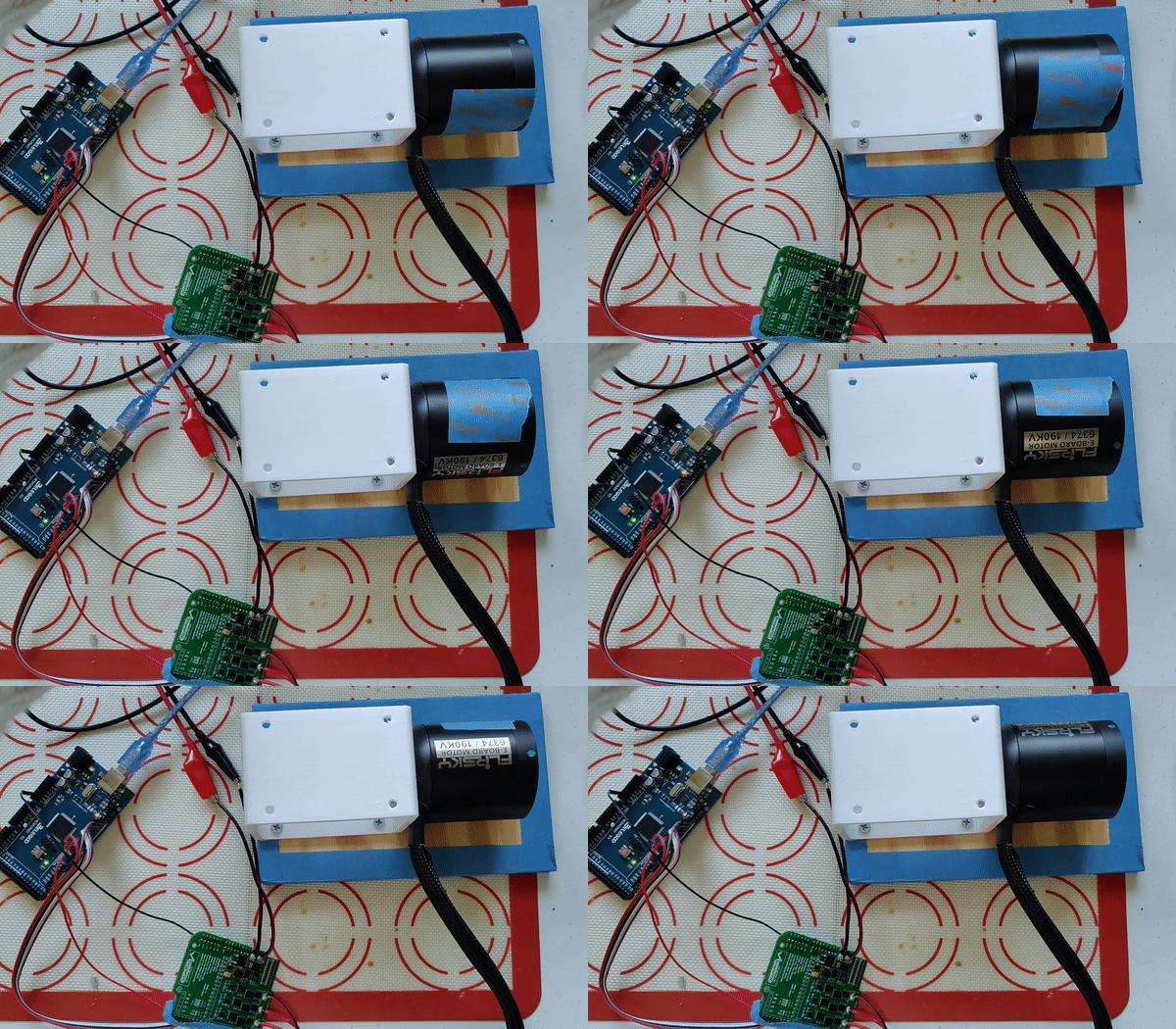
Demonstration open loop:

Low power 4 pole inrunner
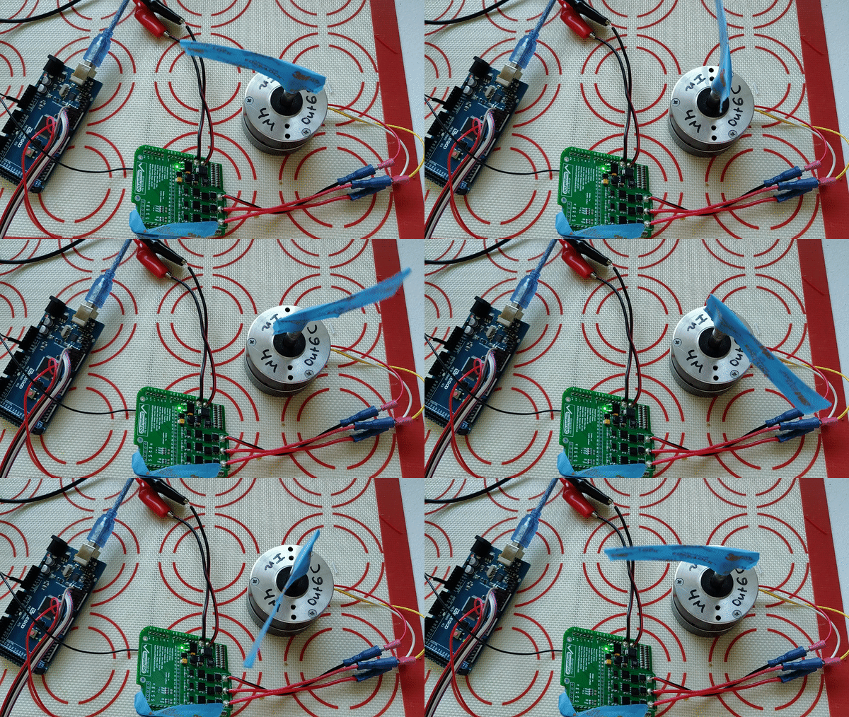
ezgif.com-gif-maker (2)

High power E-Bike outrunner

ezgif.com-gif-maker

Hoverboard outrunner

ezgif.com-gif-maker (1)

I will post later here in the same thread destructive testing as well as test the current sense.

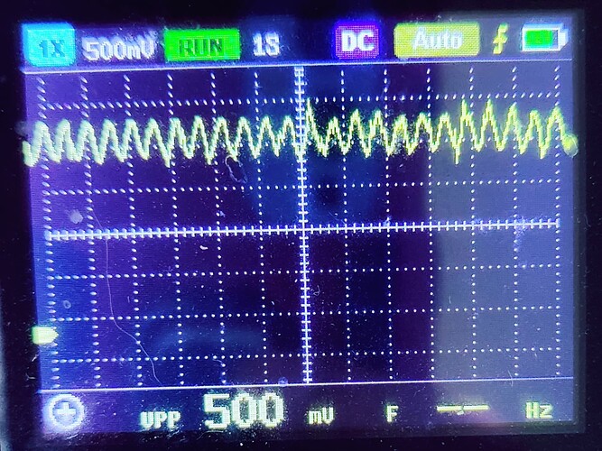
Current sensing looks pretty awesome, nicely centered around 1.15 V on all three channels.

The 30A sensor was out of stock so this test board was fabbed with I believe 20A sensor (or 10A I don’t remember?), this is the waveform on one of the channels for about 1A current. Peak-to-peak is 500mV, offset 1.15V.

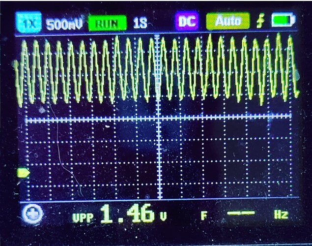
This above is the hoverboard motor current sensing. Wow, the current and torque are so high I cannot stop the motor with bare hands. I believe this board would perform best / most efficiently with motors in the hoverboard range of about 1 to 2ohm and PWM of about 15kHz.

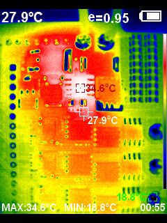
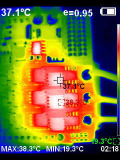
Thermals:

Low power gimbal:

image

High power hoverboard:

image

When I’m running the E-Bike motor it got very hot so I’ll attach a heatsink, reprogram the frequency down to 15k and re-take the thermal test, I don’t want to destroy the board yet.

@Antun_Skuric and @runger , please follow up.

Most important, the cost to fab this makes it pretty affordable. The shield was designed to be low cost. I believe at the moment the cost is about $15 per board for a small batch.

Stay tuned for destructive testing! I will try to make a video of the board going boom.

Cheers,
Valentine
11 Likes

Fantastic! I’m assume this will work with Nucleo boards just as easily? Would love to order a couple if you are planning a run.

This is brilliant @Valentine and perfect for my application. I’ll be following along.

I’m currently playing with rewired hoverboard motors and the current shield as an option for a small production run so this is a big step forward :+1:.

Is there any thoughts on timescale until they are likely to be available to buy?

I’ll be looking at sets of 6 to replace the BGs that I’m prototyping with due to the BG not being licensed for production.

Many thanks
Barry M

@Valentine Just wondering how this is going? Not chasing, just genuinely interested.

It’s done. It works. Since I didn’t see any interest I didn’t post any updates. What specifically you need?

Cheers,
Valentine

What’s the best way to purchase a couple of these?

I also am interested in this design. Is the version on oshwlab.com still up2date?

I’m not selling anything, unfortunately. I could, however, make them for you and you pay for the boards and shipment, if you cannot manufacture them yourself. There is no formal store or anything. Or I could walk you through the ordering process. Also, you understand, this is not a product where you could return it if you’re unhappy, or call customer support.

Cheers,
Valentine

Yes that’s the latest version. I wanted to create a fork with a G431 Nucleo you just pop in however haven’t gotten the time yet. I tested and it worked. If anyone is interested, I can fork a Nucleo version.

Cheers,
Valentine

2 Likes

@Valentine I could do with making a couple possibly more as time goes on. I’ve not used PCB way, JLC PCB or other services like that but I’ll give it a go. If you have any pointers they’d be much appreciated.

I wrote a step by step guide for the Mosquito board, just follow those.

https://community.simplefoc.com/t/ordering-a-mosquito-bldc-board-from-jlc-step-by-step/2120

Cheers,
Valentine

1 Like

I would love to get a couple of these boards, will you share the gerber file?

Thanks!

Sure. This is the link.

https://oshwlab.com/cost.co/simplefocshield_v100_copy_copy_copy

Cheers,
Valentine

1 Like

@Valentine Very nice PCB design. Thanks for sharing it. I would like to say your PCB design helped me a lot in making my own BLDC driver board.

@Valentine Can you suggest any different power driver IC, that works on 3 PWM? So, I have spare 3 PWM pins and can control another BLDC motor with the same micro controller.

Thanks

I haven’t seen a discrete driver with 3pwm. You can make your own however using a logic inverter and then rely on the driver dead-time control to artificially insert the gaps between the pulses.

Cheers,
Valentine

Hi Valentines! Excellent work on the PowerShield-D! I read that you use hall current sensors in your work. I’m pretty new to this job. At the moment I’m working on a 1 kW inverter to drive the BLT-800 with 48V voltage and 15A max current.

I used the SimpleFOC algorithm for the inverter and used a Hall Current Sensor for in-line-current sensing. Currently the code available on SimpleFOC is used for shunt current sensors.

based on that, did you modify the code for the current sensor reading? are you willing to share your code on current sensing?

Thank you.

Later on I’ll prepare an example. Cheers, Valentine

1 Like

Kindly, can you share the destructive testing results? I am planning to use this board to control the hub motor and wanted to check its maximum current handling capacity.

Also, regarding the inline current sense as the board is using integrate Hall sensor, not the shunt resistor what changes have you made in the code in order to run the motor in foc_current mode?

Thanks

My power supply maxed out, so the board won the battle at about 10A. For higher current I need to test with a 12V car battery, and I’m really busy atm.

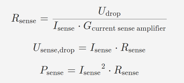
The bidirectional current sensors zero midpoint is calculated by simplefoc on the fly. Just come up with the values for the resistor and amplification to match the values of the hall current sensors which are 30A sensors (you can replace it with other chip versions with same footprint but different values during the order but do not exceed 50A, I don’t believe the copper can handle it unless you go for 2oz or higher). For example, for the bidirectional 30A current sense the calculation is as follows:

Sense resistor 1mO (0.001)
Amplification 50

Therefore this will give you about 1.6V amplification in the bidirectional case with a 3.2V swing to match your 3.3V logic to output 30A peak to through.

InlineCurrentSense current_sense  = InlineCurrentSense(0.001, 50.0, A0, A1, A2);

where An are the current sense pins on your board.

Since your goal is to get 30A amplification, you can play with the numbers and get the same result with

InlineCurrentSense current_sense  = InlineCurrentSense(0.01, 5.0, A0, A1, A2);

or

InlineCurrentSense current_sense  = InlineCurrentSense(0.1, 0.5, A0, A1, A2);

If you want to match your 3.3V swing to 30A exactly, you can try

InlineCurrentSense current_sense  = InlineCurrentSense(0.055, 1.0, A0, A1, A2);

The last setup will mean that your imaginary sense resistor/amplifier combo has a value of 55 mΩ at 1.0 amplification and drops 1.65 V at 30 A. The imaginary current sense amplifier got 1.65 V dropped by the sense resistor by G=1 , resulting in a maximum output voltage of 1.65 V

Cheers,
Valentine