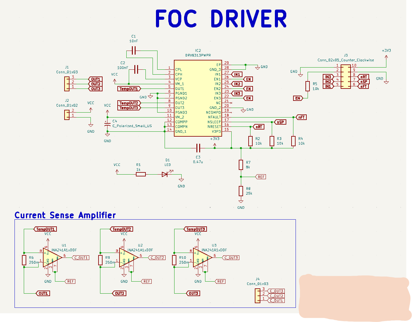
I’m making a custom pcb board based on simplefoc mini.
I just wanted to add the functionality of in-line current sensing to simplefoc mini board so I made a schematic below.
[Brief Explanation of my current sensing amps]
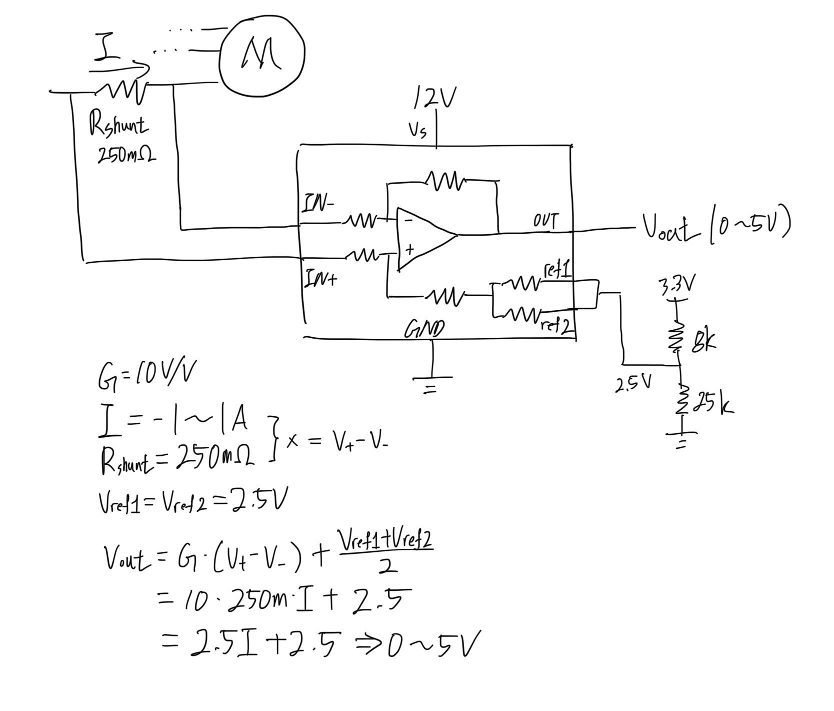
The motor I’m using has max current of 1A, and I want the Vout to have a range of 0~5V.
Since Vout = G × (Vp − Vn) + (Vref1 + Vref2)/2, I set the parameters based on my goal spec.
I would consider the range you’re using - I understand you want 0-5V output, but 0V is your bottom rail, while 5V is well below the 12V power supply. By centering on 2.5V and using 2.5V range you may come close to or hit 0V for one direction of current flow.
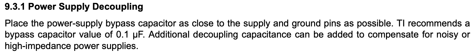
I’m not sure that’s good for accuracy, as the datasheet advises to keep the output in the linear range.
But this may be a non-issue if you never actually come close to your 1A max in practice.
I’m also concerned about this problem, but I think Arduino UNO, which I’m using for controlling the board, will require 5V input so I was trying to stick to the 5V range.
Is there a better approach for this?
And I want to ask how many layers I should use for this PCB.
Always Thanks!
Do you have to use an UNO? UNO was a great MCU but for doing FOC control its kind of slow. A nice STM32 or ESP32 chip would have much better performance for you…
Most 32 bit MCUs are 3.3V devices, so then you could centre the power on 1.5V with a 2V range or similar, leaving some small headroom to the 0-rail. Or you just try it out and see how it goes.
Hmmm you may be able to route it on 2 layers, but I’d recommend 4 to be able to have a ground plane and make sure the analog parts can be routed with some space.