Hello! As a disclaimer, I’m a complete beginner when it comes to this. I am trying to achieve closed loop velocity control of a 3 phase BLDC motor with a 3 channel hall sensor, and to that end I am using a nucleo 64 board and a SimpleFOC Drive v1.3 driver.
My main question is about the SimpleFOC Drive’s soldering pads, as I know the SimpleFOC Shields have pads that need to be soldered for them to work. I was unable to find the relevant information on the github. As I want to use the hall sensor pullups, would I just need to solder each of the pairs of pads above the pullups for them to work? Are there any other pads I should solder?
I just want to make sure of what I need to do before trying anything and potentially ruining the driver.
Thank you in advance for all the help, any extra tips when it comes to using this board is appreciated 
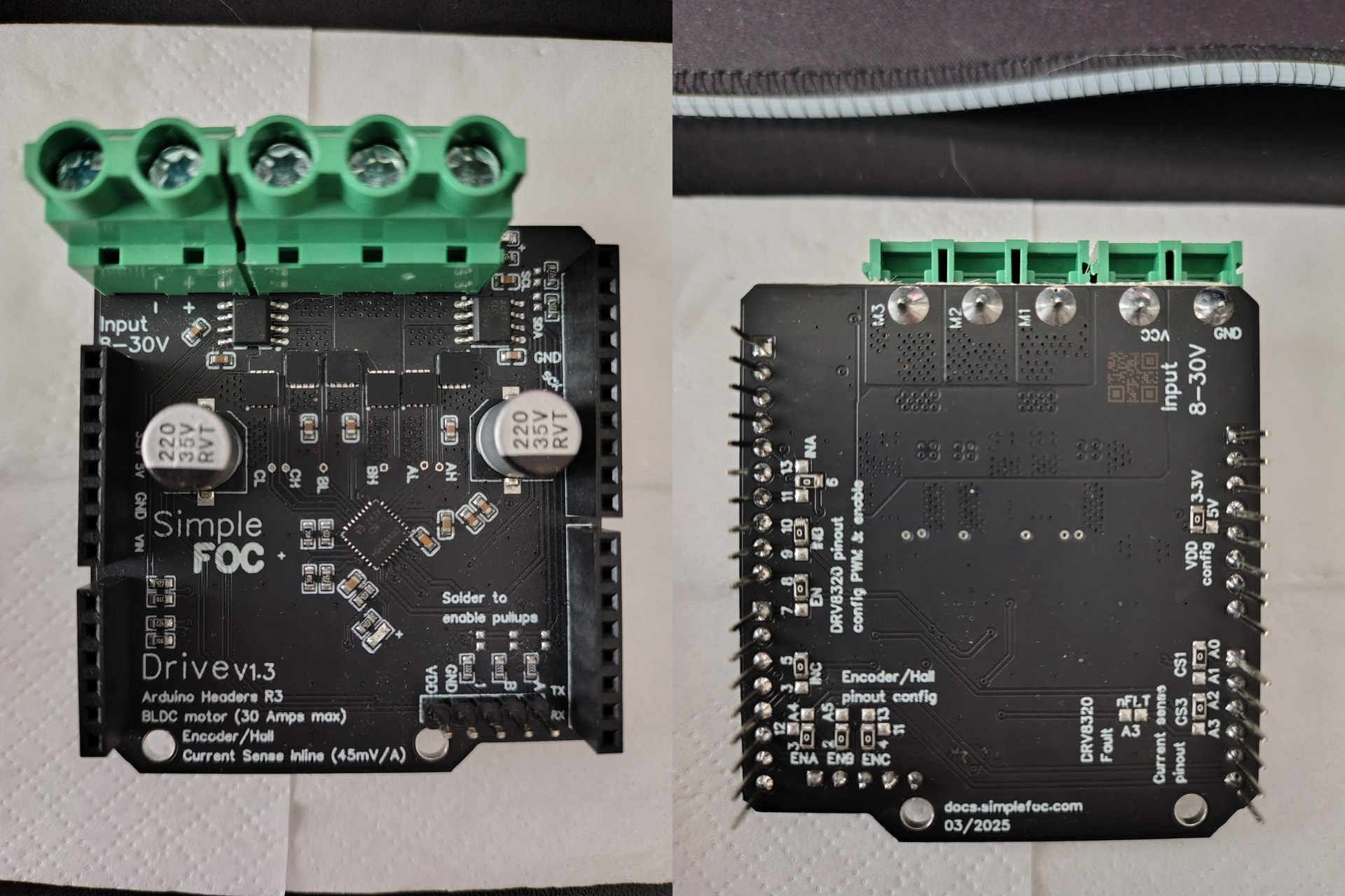
Pictures of the board:
2 Answers
2
Hi there!
Nice, we did not have the DriveShield from makerbase on the forum yet. I’m very much interested in any feedback you might have!
We are working on making them available on our side too. 
So the board has basically the same soldering scheme as the SimpleFOCShield, however Makerbase boards seem to come with the 0Ohm (short circuit) resistor presoldered so you don’t have to solder anything to get started.
Your pin-out (assuming you have the board on the picture) is:
// pins 6, 10, 5,  and enable is on 8
BLDCDriver3PWM driver = BLDCDriver3PWM(D6, D10, D5, D8);
For current sesning you can use:
// inline current sensor instance
// ACS712-30B
//   - amp gain in 66mA/V
// but there is a voltage divider 3.3/5.0 volts
//    - 4.7k and 10k -> (10/14.7) = 0.68
InlineCurrentSense current_sense = InlineCurrentSense(0.68*66.0f, A0, A2);
And if you’re using some stm32 chip I’d suggest to use low-side current sensing which is not blocking and has much better performance
LowsideCurrentSense current_sense = LowsideCurrentSense(0.68*66.0f, A0, A2);
We will be pushing the docs on this board in the coming months. Sorry about the lacking docs at the moment.
Thank you for the information!
I’ve done a few tests for my application and the board seems to be working great.
Thanks again for the help and tips!
Funny coincident... I was absent from simplefOC for about 2 years and was now looking for info about the predecessor V1.2 (Antun was very generous to send me some preproduction samples, but I haven't had a good use for them until now. ) As it seems, there are some differences (errors?) in the silkscreen of V1.2 , am I right? Are there other significant issues I should know, before powering them up? THX Olaf
– o_lampe