SimpleFOC 3PWM cannot support more than 3 motors at a time

Hello,

@runger, @Antun_Skuric

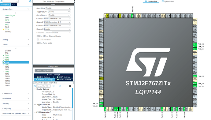
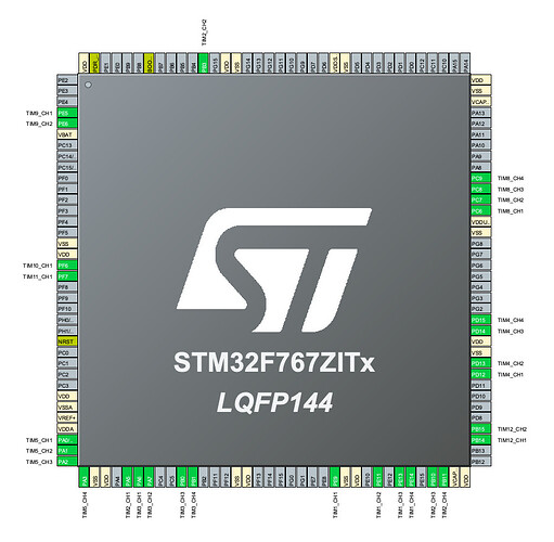
Recent questions made me curious if/how the library can support more than one motor on a 3PWM timer set. I used STM32F767 and wrote a simple open loop for the six timers supporting PWM on a single timer per set.

It appears that any timer combination is limited to only three motors at a time. Adding any fourth motor regardless of the channel halts the MCU within the

driver.init();

step, and thus the whole MCU hangs.

Is there a hard limit on three instances of the driver, or this is some inherent bug just applicable to STM32?

Below is the code I used for Nucleo-144 STM32F767ZI

Any input would be highly appreciated. I can test whatever you discover/change/fix.

Open loop motor control example for six motors.

Please uncomment any motor after the init to trigger the hangup.

Perhaps I’m doing something wrong?

#include <SimpleFOC.h>

BLDCMotor motor1 = BLDCMotor(1);
BLDCMotor motor2 = BLDCMotor(1);
BLDCMotor motor3 = BLDCMotor(1);
BLDCMotor motor4 = BLDCMotor(1);
BLDCMotor motor5 = BLDCMotor(1);
BLDCMotor motor6 = BLDCMotor(1);

BLDCDriver3PWM driver1 = BLDCDriver3PWM(PE9,  PE11, PE13); //T1
BLDCDriver3PWM driver2 = BLDCDriver3PWM(PA5,  PB3,  PB10); //T2
BLDCDriver3PWM driver3 = BLDCDriver3PWM(PA6,  PA7,  PB0);  //T3
BLDCDriver3PWM driver4 = BLDCDriver3PWM(PD12, PD13, PD14); //T4
BLDCDriver3PWM driver5 = BLDCDriver3PWM(PA1,PA2, PA3); //T5 (CH2,CH3,CH4)
BLDCDriver3PWM driver6 = BLDCDriver3PWM(PC6,PC7, PC8); //T8

//target variable
float target_velocity = 2;
float target_voltage = 5;
float maxVelo = 20; //rad/s
float maxVolt = 2;

//int analog_read_A0 = 0;
//int analog_read_A1 = 0;
unsigned long prev = 0;
unsigned long current = 0;
unsigned long threshold = 500;

void setup() {

  driver1.voltage_power_supply = 12;
  driver2.voltage_power_supply = 12;
  driver3.voltage_power_supply = 12;
  driver4.voltage_power_supply = 12;
  driver5.voltage_power_supply = 12;
  driver6.voltage_power_supply = 12;


  driver1.pwm_frequency = 15000;
  driver2.pwm_frequency = 15000;
  driver3.pwm_frequency = 15000;
  driver4.pwm_frequency = 15000;
  driver5.pwm_frequency = 15000;
  driver6.pwm_frequency = 15000;

  //driver.enable_active_high = false; // Reverse logic driver, low is enable

  // driver init creates a hangup for more than 3 drivers
  //driver1.init();
  driver2.init();
  driver3.init();
  driver4.init();
  ///driver5.init();
  driver6.init();

  //motor1.linkDriver(&driver1);
  motor2.linkDriver(&driver2);
  motor3.linkDriver(&driver3);
  motor4.linkDriver(&driver4);
  //motor5.linkDriver(&driver5);
  motor6.linkDriver(&driver6);

  //motor1.voltage_limit = target_voltage;   // [V]
  motor2.voltage_limit = target_voltage;   // [V]
  motor3.voltage_limit = target_voltage;   // [V]
  motor4.voltage_limit = target_voltage;   // [V]
  //motor5.voltage_limit = target_voltage;   // [V]
  motor6.voltage_limit = target_voltage;   // [V]

  //motor1.velocity_limit = target_velocity; // [rad/s] cca 50rpm
  motor2.velocity_limit = target_velocity; // [rad/s] cca 50rpm
  motor3.velocity_limit = target_velocity; // [rad/s] cca 50rpm
  motor4.velocity_limit = target_velocity; // [rad/s] cca 50rpm
  //motor5.velocity_limit = target_velocity; // [rad/s] cca 50rpm
  motor6.velocity_limit = target_velocity; // [rad/s] cca 50rpm

  //motor1.controller = MotionControlType::velocity_openloop;
  motor2.controller = MotionControlType::velocity_openloop;
  motor3.controller = MotionControlType::velocity_openloop;
  motor4.controller = MotionControlType::velocity_openloop;
  //motor5.controller = MotionControlType::velocity_openloop;
  motor6.controller = MotionControlType::velocity_openloop;

  //motor1.init();
  motor2.init();
  motor3.init();
  motor4.init();
  //motor5.init();
  motor6.init();

  _delay(500);
  prev = millis();
  current = millis();
}

void loop() {

   //motor1.voltage_limit = target_voltage;
   motor2.voltage_limit = target_voltage;
   motor3.voltage_limit = target_voltage;
   motor4.voltage_limit = target_voltage;
   //motor5.voltage_limit = target_voltage;
   motor6.voltage_limit = target_voltage;

   //motor1.move(target_velocity);
   motor2.move(target_velocity);
   motor3.move(target_velocity);
   motor4.move(target_velocity);
   //motor5.move(target_velocity);
   motor6.move(target_velocity);

}

Cheers,
Valentine
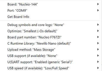
Upon further investigation, it appears the Arduino optimizer has an inherent problem when compiling with the defaults. When compiling/linking with no optimization, the issue seems to disappear. I will investigate further. Stay tuned.

Upon even further investigation, when compiling/building with no optimization, I was able to make 4 motors run at the same time in open loop. Adding any 5-th motor would create a problem.

Any idea why that could be? You don’t even need to attach motors, PWM on the oscilloscope will show the problem immediately.

Cheers,
Valentine

Hey @Valentine ,

There is a number of things to note here:

  1. Speaking only in terms of the PWM capabilities, i.e. ignoring sensors and other peripherals that might need pins, F767ZI should be able to handle 6 motors in 3-PWM for sure on TIM1, TIM2, TIM3, TIM4, TIM5 and TIM8. I think it can even handle 2 more, by using the 4th PWM channel of all these channels you get another 6 PWM pins. And then you could use another 2 PWM pins each on TIM9 and TIM12, and one more each on TIM10 and TIM11, for another 2 motors, bringing the grand total to 10 motors in 3-PWM mode. TIM13 and TIM14 would have 1 more PWM channel each, but just 2 more it’s not enough. The LPTIM, TIM6 and TIM7 don’t support PWM.

  2. the clock configuration of the F767 is already fairly complex, so I would not necessarily rely on default arduino getting it right.

  3. personally I don’t think I’ve ever tested using TIM10 or TIM13 for example… YMMV…

  4. I fear we have introduced a bug recently with the timer synchronization in relation to multiple motors. In a recent test I did on F412, the order I initialised the drivers had an impact on whether it works or not. You may be better off with version 2.3.2 of SimpleFOC when testing multiple motor setups on STM32.

  5. Please set -DSIMPLEFOC_STM32_DEBUG and include the serial output from the driver initialisation. It should tell you exactly what went wrong with the timer pin configuration…

  6. To use more than 4 motors in 3-PWM or more than 2 motor in 6-PWM, please set
    -DSIMPLEFOC_STM32_MAX_PINTIMERSUSED=20
    (or even more).

    This is the max number of PWM pins you can use with SimpleFOC across all motors. The default is 12, which explains why you can only initialize 4 motors at the moment.

1 Like

@runger:

Awesome, I’ll try everything and come back to report!

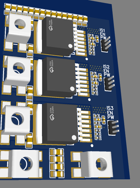
I got this really crazy idea to check how many simultaneous 3pwm motors can be handled with a single H series MCU. I’m in the process of re-creating a really simple 3PWM test board using the infamous IFX007 to string them up and tryout.

Mhhwwaaaahahahahahahahaha!

But seriously, I’ll only try hall sensors voltage/velocity, else dealing with multiple SPI and sensoring multiple motors would genuinely be a crazy idea. As a proof of concept though closed loop hall sensor setup should give a good idea of the baseline and could be done on a weekend. Plenty of hall sensor pins on that board.

Cheers,
Valentine

1 Like

I’m super busy but managed to make it work.

Got the driver developed based on IFX007, and tried all 6 PWM with this build option (create build_opt.h in the ino directory) and no optimization, and now I can control 6 motors with one MCU.

I’ll come back later to post the setup, my time is of very short supply, but I proved we can simultaneously control up to 6 motors with one MCU. I’ll try later with more than 6 based on @runger 's feedback.

Cheers,
Valentine

1 Like

@runger

Wouldn’t the timers be off-key if we use two timers for one motor? Or we are synchronizing the timers?

Cheers,
Valentine

They are synchronized since the last SimpleFOC release…

1 Like

Right, however you mentioned to use a previous version just in case so I wasn’t sure which one was which.

@runger Thank you. I guess I will end up testing this.

One thing I discovered, the library / timers are extremely sensitive to the level of optimization when compiling/building. Different MCUs break the library handling of multiple timers depending on the level of optimization selected. To make the same code work on two MCUs I need to select a very particular optimization type, different for each MCU. We are talking STM32. This type of “black magic” means something is not quite right there.

I’ll post a better description of the problem when I get the time. The real problem is that I use a custom built MCU board for one of the tests, so I guess my case is very edge/obscure. Reproducing requires the exact MCU/pin breakout (144pin f103).

Cheers,
Valentine

Interesting that optimization breaks things, but nice work on getting 6 going!

You’ll run into even more trouble if you try current sensing, the backend ADC handling really isn’t designed around more than one motor. Closed loop using the timer encoder mode and an AB quadrature encoder should work fine though, assuming you use voltage mode for torque control. I think several stm32’s support hardware hall sensor decoding, but I forget which ones.

1 Like

I have an idea about this, I think it’s possible for the timer rating system to chose a timer that’s already been allocated to a motor. If this happens, it doesn’t update the previously initialized motor. Once a timer channel has been allocated to a motor, it should be removed from the list of available timer channels. I’m not sure if that’s what you’re seeing, but I think that’s what I saw when doing multiple motors.

I may have found this bug, though it isn’t recently introduced. In _alignTimersNew(), there’s a local array HardwareTimer *timers[numTimerPinsUsed];

As far as I know, it’s not legal to use a variable as the length of an array in C++, though I’m not 100% sure when it’s in a function. You can do variable-length stack allocations in assembly, but you have to keep track of the original stack pointer and the address of each thing you allocated. As far as I know, C++ compilers always allocate fixed sizes so the generated code can access them with immediate offsets relative to the stack pointer. I wish I knew how to get Arduino to save the assembly files so I could check exactly what it’s doing in this case. But certainly the safer option would be to change that array size to the constant SIMPLEFOC_STM32_MAX_PINTIMERSUSED.

I think this is ok. Since cpp14 the size specifier can be a “a converted constant expression”

https://en.cppreference.com/w/cpp/language/array

https://en.cppreference.com/w/cpp/language/constant_expression
(see 10. an lvalue-to-rvalue implicit conversion, refer also to example code)

It’s probably not the safest way to code this, but I don’t think it’s the cause of the bug.

For me, reversing the order of initialization of the motors solves the problem, which leads me to believe it has to do with which timer can trigger which other timer…

I think one thing might be wrong with the timer alignment implementation.

It might try to align all timers from different motors, while aligning timers from a same motor might be enough. But I had no time to investigate further.

Yes, it’s the case.

From a power perspective it would be better if the PWM of 2 motors were out of phase rather than in phase, I think.

This could be done by still aligning the timers, but starting the timers with a different counters.

Bigger bulk capacitance and more low esr caps near the mosfets would solve this. No need to stagger the PWM phases across motors.

Cheers,
Valentine

It still looks like it needs to be knowable at compile time. The second case in that example code:

    std::size_t n = 50;
    const std::size_t sz = n;
    int tab2[sz]; // error: sz is not a constant expression
                  // because sz is not usable in constant expressions
                  // because its initializer was not a constant initializer

Our numTimerPinsUsed is modified dynamically before calling alignTimersNew, so unless the compiled code is able to do true variable-size stack allocation, I have no idea what it will do. Surprising it doesn’t give an error, actually.

Another bad practice is that numTimerPinsUsed isn’t initialized where it’s declared, so it’s just assumed zero before the call(s) to the configurePwm functions increment it. Uninitialized globals are usually cleared to zero at startup, but I’m not sure it’s explicitly required, so may be skipped with optimizations turned on.

But viewed the other way, staggering the phases would allow using smaller capacitors.

Hmmm you’re right, I need to look into this more. But clearly it’s not an issue or the compiler wouldn’t accept it.

Probably it’s working because these are just C functions and not objects, but maybe there’s another reason to do with whatever compile flags are set.

I don’t like the global variable being used in this way for a number of reasons, it’s not a good pattern.

Success! You can stick the -S option in boards.txt GenG0.build.st_extra_flags

The build fails overall, but the .cpp.o files in the build folder contain the generated assembly code.

Here is _alignTimersNew():

	.section	.text._Z15_alignTimersNewv,"ax",%progbits
	.align	1
	.global	_Z15_alignTimersNewv
	.syntax unified
	.code	16
	.thumb_func
	.type	_Z15_alignTimersNewv, %function
_Z15_alignTimersNewv:
	@ args = 0, pretend = 0, frame = 8
	@ frame_needed = 1, uses_anonymous_args = 0
	push	{r0, r1, r2, r4, r5, r6, r7, lr}
	mov	r2, sp
	ldr	r6, .L57
	add	r7, sp, #0
	ldr	r3, [r6]
	lsls	r3, r3, #2
	adds	r3, r3, #7
	lsrs	r3, r3, #3
	lsls	r3, r3, #3
	subs	r3, r2, r3
	mov	sp, r3
	movs	r3, #0
	mov	r5, sp
	movs	r4, r3
	str	r3, [r7, #4]
.L52:
	ldr	r3, [r7, #4]
	ldr	r2, [r6]
	cmp	r3, r2
	bge	.L55
	lsls	r2, r3, #2
	ldr	r3, .L57+4
	ldr	r3, [r2, r3]
	ldr	r0, [r3, #4]
	bl	_Z15get_timer_indexP11TIM_TypeDef
	ldr	r3, .L57+8
	lsls	r0, r0, #2
	ldr	r3, [r0, r3]
	ldr	r2, [r3]
	movs	r3, #0
.L51:
	cmp	r3, r4
	beq	.L49
	lsls	r1, r3, #2
	ldr	r1, [r5, r1]
	cmp	r1, r2
	beq	.L50
	adds	r3, r3, #1
	b	.L51
.L55:
	movs	r6, #0
.L48:
	cmp	r4, r6
	beq	.L56
	lsls	r3, r6, #2
	ldr	r3, [r5, r3]
	adds	r6, r6, #1
	movs	r0, r3
	str	r3, [r7, #4]
	bl	_ZN13HardwareTimer5pauseEv
	ldr	r0, [r7, #4]
	bl	_ZN13HardwareTimer7refreshEv
	b	.L48
.L56:
	movs	r6, #0
.L53:
	cmp	r4, r6
	beq	.L47
	lsls	r3, r6, #2
	ldr	r0, [r5, r3]
	bl	_ZN13HardwareTimer6resumeEv
	adds	r6, r6, #1
	b	.L53
.L49:
	lsls	r3, r4, #2
	str	r2, [r3, r5]
	adds	r4, r4, #1
.L50:
	ldr	r3, [r7, #4]
	adds	r3, r3, #1
	str	r3, [r7, #4]
	b	.L52
.L47:
	mov	sp, r7
	@ sp needed
	pop	{r0, r1, r2, r4, r5, r6, r7, pc}
.L58:
	.align	2
.L57:
	.word	.LANCHOR2
	.word	.LANCHOR3
	.word	HardwareTimer_Handle
	.size	_Z15_alignTimersNewv, .-_Z15_alignTimersNewv
	.global	__aeabi_i2f
	.global	__aeabi_fdiv
	.global	__aeabi_fmul
	.global	__aeabi_f2uiz
	.global	__aeabi_uldivmod
	.global	__aeabi_ldivmod
	.global	__aeabi_lmul
	.global	__aeabi_fcmpgt

It does indeed do a variable-length stack allocation. Original sp is stashed in r7 and restored at the end. .LANCHOR2 at .L57 is numTimerPinsUsed (after tracing through some other stuff in the file), so it loads that, multiplies by 4 bytes per array entry, rounds up to 8 bytes for whatever reason, and subtracts from stack pointer (temporarily copied to r2).

So you can indeed use variable-length arrays inside functions! I never knew.

1 Like