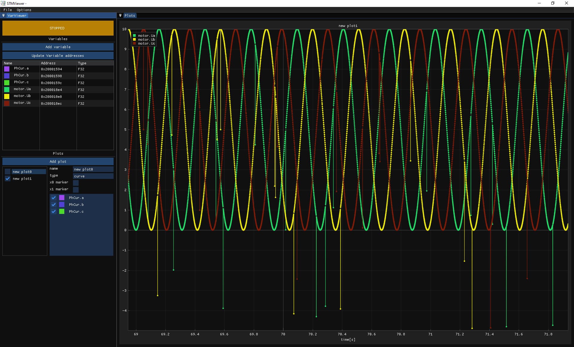
Not sure, if this is a bug or not, but since the update from v2.3.1 to 2.3.2 I see some strange outliers in the phase voltages (see below). Plotted are the variables motor.Ua, motor.Ub and motor.Uc. Hardware is a B-G431B-ESC1 with SPI encoder (AS5047P). I cannot exclude problems with stmviewer, but did not observe this with v2.3.1 or 2.3.0.
Hey, thanks for reporting it!
Compared to 2.3.1, I don’t think anything was changed on the PWM side for the B-G431-ESC1. There have been several changes on the current sensing side…
There has been a change in the space vector modulation code, but this looks like SinePWM?
Presumably there are some 0-values in the data leading to these outliers?
If we’ve introduced a bug with the new release it would be good to find it quickly, but on the other hand I would have said many people were actually using the dev branch on various STM32G431 MCUs…
Are there corresponding outliers in the sensor data, if you plot that? Could it be a sensor problem?
Hi, just to be sure
It could be new sine/svpwm code is just adding values to ua ub and uc, and Stmviewer samples at the wrong moment.
Example:
Ua = 1 + 1;
Ua += 1;
Stmviewer could sometimes sample between the 2 statements.
If this was not the case before, that could just be it! Thanks for the hint! My example was sine PWN, openloop velocity. Apart from seeing the outliers, I do not notice anything strange, so probably @Candas1 is right!
The outliers are always the expected value - 5 which is the center.
It has no impact but I could use local variables and then set motor.ua
It’s also a good use case for the trace viewer in stmviewer, @drbruce from discord and I have been experimenting with it. We can share an example.
Can you control the sample-time in STMviewer in some way? Because there are several values which are updated by calculations like you describe, where it doesn’t make sense to sample during the calculation.
It also doesn’t make sense to sample vector quantities like abc currents, dq currents, dq voltages, etc until all dimensions of the vector have been updated…
I’d be very happy is this turned out to be the explanation, because then it means we don’t have a bug ![]()
No, the variable viewer in stmviewer is polling the variable values from memory in an asynchronous way, you don’t get to chose when this happens, but the benefit is that you don’t have to change anything in your code except making a variable global if it’s not.
The trace viewer reads data pushed out via SWO in a synchronous way. For this you need:
- to connect the stlink SWO to the chip’s SWO (PB3), it’s the case on nucleo boards, but it’s often not the case on other boards. I suggest you populate it on your designs

- enable the Instrumentation Trace Macrocell and set the values you want to trace (example). The traces are even timestamped by the hardware.
So the trace viewer is much better for tracing time critical values but it requires specific hardware and change in software.
Just another example I saw while going through the code.
If the voltages are being limited/saturated here, you should also see strange voltages in stmviewer.