I just tried to install the simpleDCmotor library and got a message:
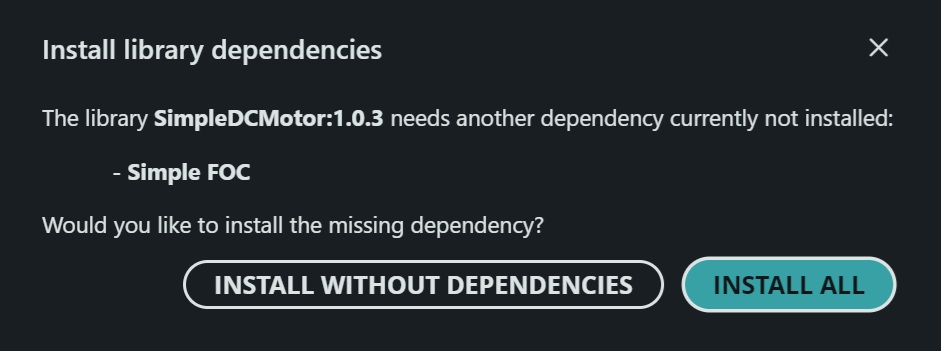
I’m absolutely sure the latest simpleFOC library is installed, but does the DCmotor lib require a different (older ) lib?
I just tried to install the simpleDCmotor library and got a message:
I’m absolutely sure the latest simpleFOC library is installed, but does the DCmotor lib require a different (older ) lib?
Yes, it is very out of date, and fairly incomplete too. I updated it last month in preparation for use on my stepstick, but haven’t actually tested it yet. If you want to be the guinea pig, here it is: GitHub - dekutree64/Arduino-FOC-dcmotor at dev · GitHub
Click the <>Code button and Download ZIP and unzip it into your Arduino libraries folder.
It should work with estimated_current and dc_current modes now, so you can do torque control with or without current sense rather than only voltage control like before.
It requires a couple changes to SimpleFOC as well. In FOCDriver.h, add DC in the DriverType enum:
enum DriverType{
    UnknownDriver=0,
    BLDC=1,
    Stepper=2,
    Hybrid=3,
    DC=4
};
And in CurrentSense.cpp getABCurrents(), replace the check for DriverType::Stepper with this:
    // check if driver is an instance of StepperDriver or DCDriver
    // if so there is no need to Clarke transform
    if (driver_type == DriverType::Stepper)
        return (ABCurrent_s){current.a, current.b};
    else if (driver_type == DriverType::DC)
        return (ABCurrent_s){current.a, 0};
That’s awesome! Running it with estimated_current means, I can define the DCmotor with polepairs, phase resistance and kV?
Actually it is a ZS-X11H BLDC driver, which allows analog or PWM openloop-velocity control.
With the hallsensors as feedback, I hope to make it closed loop velocity.
The DCdriver class 1PWM/1 Dir sounds like a good fit.
I made the changes and rewrote the velocity example file for my needs. It compiles without errors!
I wasn’t able to define DCmotor with pole pair, but the hall sensor class knows it’s 4PP.
The Direction pin logic is still unclear: does it expect positive target: dir = high? > CW or CCW
Maybe I should use the driver class 1PWM and take care of the dir-pin elsewhere
I tested motor and driver with a generic PWM signal and I got almost full RPM.
The PWM input doesn’t like 100% duty cycle I guess.
But with the simpleDC motor library, I had no luck. I tried torque:: voltage mode and estimated_current, both leave the motor limp
/**
 * Velocity control example.
 * This example controls a BLDC motor via a 1PWM-1DIR-compatible driver hardware,
 * such as ZS-X11H driver.
 * The example is using a 42- or 57-BLF 01-03 BLDC motor with 8 poles and hall sensors
 *
 * SimpleFOC's velocity mode is used to move the motor at specific speeds
 * set by the user. Positive or negative values determine the direction of
 * rotation. The velocity is expressed in radians per second.
 *
 * SimpleFOC's commander object is used to enable serial control of the
 * desired speed. After connecting the serial console, type "M100" to
 * set the speed to 100 rad/s, or "M-2.5" to set it to negative 2.5
 * rad/s.
 * Many other motor parameters can be set via the commander, please see
 * our documentation for details on how to use it.
 *
 */

#include <Arduino.h>

#include "SimpleFOC.h"
#include "SimpleFOCDrivers.h"
#include "SimpleDCMotor.h"
#include <encoders/smoothing/SmoothingSensor.h>

// DCMotor object
DCMotor motor = DCMotor(1.1f, 167.0f);	//	matches 42BLF01

// DCDriver object
// there are different types to choose from, please select the correct one
// that matches your motor driver hardware.
DCDriver1PWM1Dir driver = DCDriver1PWM1Dir(5, 4);

// Sensor object
// **** MAKE SURE THE PINS ARE 5V COMPATIBLE, BECAUSE THE ZS-X11H HAS 5V PULLUPS ONBOARD ****
HallSensor halls = HallSensor(6, 7, 8, 4); // Pins A, B, C, PP
void doA() { halls.handleA(); }
void doB() { halls.handleB(); }
void doC() { halls.handleC(); }

SmoothingSensor smooth_sensor(halls,motor);

Commander command = Commander(Serial);
void doMotor(char* cmd) { command.motor(&motor, cmd); }

void setup() {
  Serial.begin(921600);
  while(!Serial){};

  // Initialize sensors
  smooth_sensor.phase_correction = -_PI_6;

// maximal expected velocity
  //halls.velocity_max = 500; // 1000rad/s by default ~10,000 rpm
  halls.init();
  halls.enableInterrupts(doA, doB, doC);

  char motor_id = 'M';
  command.add(motor_id,doMotor,"motor");
   // configuring the monitoring to be well parsed by the webcontroller
  motor.monitor_start_char = motor_id; // the same latter as the motor id in the commander
  motor.monitor_end_char = motor_id; // the same latter as the motor id in the commander

  // enable debug output to the serial port
  //SimpleFOCDebug::enable();

  // basic driver setup - set power supply voltage
  driver.voltage_power_supply = 24.0f;
  // if you want, you can limit the voltage used by the driver.
  // This value has to be same as or lower than the power supply voltage.
  driver.voltage_limit = 24.0f;
  // Optionally set the PWM frequency.
  driver.pwm_frequency = 10000;	//	up to 20kHz is possible
  // init driver
  driver.init();
  // init sensor
  halls.init();
  // link driver to motor
  motor.linkDriver(&driver);
  // link sensor to motor
  motor.linkSensor(&smooth_sensor);

  // set a voltage limit on the motor, optional. The value set here
  // has to be lower than the power supply voltage.
  motor.voltage_limit =  0.9f* driver.voltage_limit;
  motor.velocity_limit = 500.0f;
  // control type - for this example we use velocity mode.
  motor.controller = MotionControlType::velocity;
  motor.torque_controller = TorqueControlType::estimated_current;
  // init motor
  motor.init();

  // set the PID parameters for velocity control.
  motor.PID_velocity.P = 1.0f;
  motor.PID_velocity.I = 0.0f;
  motor.PID_velocity.D = 0.0f;

  motor.PID_velocity.output_ramp = 200.0f;
  // low pass filter time constant. higher values smooth the velocity measured
  // by the sensor, at the cost of latency and control responsiveness.
  // Generally speaking, the lower this value can be while still producing good
  // response, the better.
  motor.LPF_velocity.Tf = 0.001f;
  // set the target velocity to 0, we use the commander to set it later
  motor.target = 0.0f;
  // enable motor
  motor.enable();

  motor.useMonitoring(Serial);
  motor.monitor_variables = _MON_TARGET | _MON_VEL ;  //| _MON_ANGLE;
  motor.monitor_downsample = 500;

  //motor.motion_downsample = 10;      // slower move() updates

  Serial.println("Initialization complete.");
}

void loop() {

  smooth_sensor.update();

  // call motor.move() once per iteration, ideally at a rate of 1kHz or more.
  // rates of more than 10kHz might need a delay, as the sensor may not be able to
  // update quickly enough (depends on sensor)
  motor.move(); // target speed can be set via commander input

  // call commander.run() once per loop iteration, it will process incoming commands
  command.run();

  // call motor.monitor() once per loop iteration, it will print the motor state
  motor.monitor();
}
I don’t think the motor pole_pairs setting will do anything since the physical number has no effect on how it runs. Only the resistance and kv are needed to estimate the current.
HallSensor pole_pairs should be 1 if it’s sensing a single magnet glued to the end of the shaft. But that will only give 6 steps per revolution, so I’d recommend using 49E linear halls.
Dir high does correspond to positive voltage on DCDriver1PWM1Dir, but with BLDC driver hardware you’ll want to connect the motor wires to two of the half-bridge outputs and use DCDriver2PWM. Positive commanded voltage sets phase B to 0V and PWM’s phase A, and negative commanded voltage sets phase A to 0V and PWM’s phase B (so A is relatively lower voltage, effectively negative).
There is a disk on the motor shaft with 8 magnets.
I added motor.initFOC() and motor.loopFOC() but the code gets stuck at initFOC.
Funny enough, now the motor spins with a slow steady pace. Seems like the PWM-pin is alive.
Although all PID values and motor.target are 0.0
That should be ok then.
Not surprising since that initFOC is 100% untested. But the only place I see to get stuck is if voltage_sensor_align is not enough to get the motor moving, then do {angle = sensor->getAngle();} while(abs(angle-start) < _PI/12); will never finish. I need to add a timeout on that (and for the similar loop in the index search). If you want to take the guesswork out of it, try running TorqueControlType::voltage without initFOC and find a voltage that will reliably move without drawing excessive current.
Odd that it would spin when not commanded. Are you using TorqueControlType::estimated_current mode? Sometimes it will do that if the resistance and kv aren’t quite right, although usually not until you’ve already started it moving.
I tested initFOC with
motor.zero_electric_angle = 0.0f;
motor.sensor_direction = Direction::CCW;
and it still doesn’t go further.
There is another issue related to the dir-input of ZS-X11H. I think I need a 5V level shifter or optocoupler for it. When the dir pin is high, the driver-board LED lights up and the rp2350 browns out.
I will put that project on the slow burner, it was just a gap filler anyway until my 3D printed parts were ready.
Let me know if I can test any new findings, I won’t rip it apart soon