Hi All,
I am new to this forum and found many interesting projects and ideas to run BLDC motors and implementing the Simple FOC algorithm.
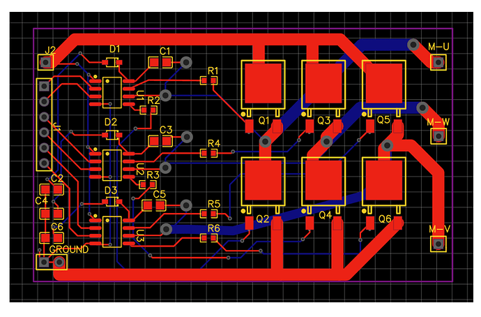
I have developed a simple BLDC driver circuit board using N-Channel Mosfet and half-bridge gate driver IC. I am using timing interrupt along with software interrupt at Arduino mega for switching the Mosfet. By varying the PWM signal, I am able to move the motor and change it’s spread.
Now, I want to Implement the Simple FOC on it but need a bit of advice. Currently, I am applying 3 PWM signals on the High-end side of the driver IC while just enabling the Lower end of the IC by a simple HIGH/Low command of the Arduino.
My question is to implement the FOC do I have to use the 6 PWM command or the 3 PWM command. Also, in the majority of the example, the voltage limit is set to 1 what is the reason for that?
My apologies, if it seems like a basic question but I am new to BLDC motors and slowly learning about it.
The Mosfet I am using are IRLR784TRPBF, Date Drive IC: IR2101sTRPBF, MC: Arduino Mega, BLDC Motor: Hall sensored 8 poles 52 Watt
It will not work. IR2101 needs 6 active PWM signals. It is not a good chip for your application and also your PCB-design is faulty.
Dear Jan_Donker,
Many thanks for your reply. Kindly, if you can advise me regarding the Fault of my PCB and what should be corrected.
thanks
Hello @MoidKhan
This is an interesting board you have. Reading the documentation of IR2101 it appears you will need 6 PWM. Also, it is difficult to tell anything about the design because you need to post the schematics, the PCB alone is hard to decipher because the elements have no values and traces are hard to follow. The reason for the 1v limit in the example code is to limit the voltage so you don’t over-heat or burn your motor, if your design is good and you make it work, you can increase the voltage tot he maximum in the code.
Cheers.
Hey @MoidKhan ,
It is possible to do 6 PWM control with some MCUs supported by the library, such as the ESP32, so it should be possible to use the IR2101. You should read upon it and make sure to insert proper dead times for each complementary PWM signal, and if you have an oscilloscope make sure the complementary PWM signals look OK before you try to use your board to move a motor. If this is a board you have already made I believe you should be able to use it with SimpleFOC.
This is to limit the current as many brushless motors have a low resistance, usually this is NOT the case for gimbal motors and the limit tends to be much closer to the bus voltage.
Good point.
@MoidKhan , you may want to read this link below and check for the dead time, since this driver is very basic and doesn’t set/check it for you, and the default SimpleFOC 6PWM dead time may not be sufficient and you may get some, shall we say, interesting results if you get shoot-throughs.
Definitely an oscilloscope is needed.
Hi Valentine,
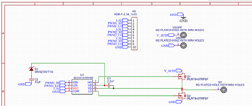
Many thanks for your reply. Please find below the schematic of the circuit.
Currently, the circuit works by applying PWM signal from the MC to the high voltage side (HV) of the driver and simple state high/low command on the low voltage side (LV). I will test this circuit on the 6PWM of the SimpleFOC library.
Thanks for explaining about the voltage limit.
Regards,
Moid
Hi David,
I understand that IR2101 is a basic motor driver just wanted to check will simple FOC library work on it. As Arduino Mega has 15 PWM signal. So will used timer 2,3,4 PWM signal to control the driver.
Thanks for telling about the dead time. I will check it by using Oscilloscope. I will post the outcome of my board, how it reacts when applying simple FOC library with 6PWM.
Thanks,
Moid
1 Like
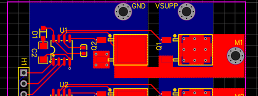
I reviewed your board. You do have a few issues.
I am posting a quick check on it, see if you can find the differences. I will try to do a bit more if I get the time.
Cheers.
1 Like
Many thanks for highlighting the issue. I will try to start to make these changes in my board.
If I get the time I could make this public, but you need to finish it. Also there is absolutely no guarantee it will work, as I used your components and schematics, except the diode where I had no idea which one you used, so I just placed one at random. As you could see my schematics of your design are incomplete. You need to finish the rest.
I will try to finish it also I have one question, did you use two layer or three layer on the PCB. I understand the beneath blue you made all ground but the Vsupp as well. Apologies if it’s a basic design question but I am understanding it. Thanks
Two layers. EasyEDA doesn’t do 3 layers, only 2,4 or 6. One thing you need to notice, the vias under the pads are generally a no-go however I found if the vias are sparse and under a plate pad, the DFM will pass. JCL won’t be happy but they won’t reject the design.
Thanks got it. Much Appreciated.
Got some time, added a decoupling capacitor. You need to fix the proper diodes. Good luck. Please don’t kill yourself.
https://oshwlab.com/cost.co/driver_mosfet_dev
1 Like
I don’t want to spoil the party, but this will not work either. You are right about the driver-chip needing his own power-rail, but according to specs it needs 10 to 20 volts.
Because it is a high-voltage driver. The problem is : the used mosfets are low-voltage types which will not do well when driven way above gate turn on voltage.
The best solution would be to use a different driver-ic.
@Jan_Donker
Perhaps. The specs say this:
VCC Low side and logic fixed supply voltage -0.3 to 25
Vlo Low side output voltage -0.3 to VCC + 0.3
VIN Logic input voltage (HIN & LIN) -0.3 to VCC+ 0.3
Which means if he is using 5v Arduino he can try 5V Vcc. If it doesn’t work, he can take separate input and supply anything between Vcc 10 and 20v, with the PWM at 5v, but the idea is to have a separate rail for the Vcc from the mosfet. I put 3.3v because I was in a hurry to copy/paste my nets, not because he needs to put 3.3v. Also if you look carefully I spec-ed the capacitors at 50V so he is quite safe.
That’s for him to discover, it’s part of the learning process.
As far as the mosfet voltage, as long as he stays under 20 volts who cares. The mosfet will work. I seriously doubt he will plug this into a 600v power outlet.
Many thanks for correcting the PCB. Yes, I will be using a separate power rail for Mosfet and the max Volage which I will apply is going to be 18 V.
IR2103STRPBF is the same price but Vcc is 5 to 20v and has internal dead time .
If I had knew about the Dead time from beginning I would have ordered these. Thanks for telling about them, I will order them as well. Currently, waiting for the new PCB.


