I’m trying to develop a BLDC motor driver based on VESC 75_300 System, up on my initial testing the entire hardware works fine except the INA240A3D IC, its starts heating up and leading to short circuit. I came to know that when the IC is been powered without connecting the shunt resistor with IN+ and IN-, they are working fine, but when I connect the shunt resistor and apply some load to it, they started heating up and getting short circuited.
It’s hard to say from the schematics what’s going on…
Is it an original TI part that was reliably sourced?
What voltage are you operating at? The INA240 has a CMR of -4-80V…
Which package are you using, and does it match the schematics? Looks like the schematics match the D variant SOIC package.
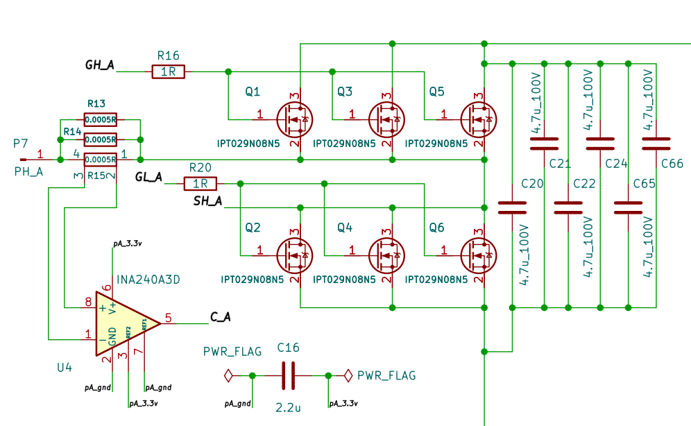
If your shunts are like in the schematics, the shunt resistance is very low - just microohms - 0.00017Ohms. The expected trace resistance between the shunt and the amplifier is probably more. What kind of currents are you trying to measure?
Hi runger, and Thanks for your gratitude on welcoming me to the community!
I think it’s a reliable source, I ordered from Digikey.
The Device operates on 48V DC. It’s D variant SOIC package.
I Will describe what kind of issue I’m facing through,
I’m a newbie developing a BLDC Driver for a 8kw motor, I have used VESC controller 100V 250A variant. So I thought of giving a try to develop my own driver based on VESC system, then I took the schematics of VESC 75V 300V variant available in their website.
Everything is working fine, except the current sensor circuitry, I couldn’t figure out exactly what’s happening, when I power the IC (current amplifier) without connecting shunt resistor to IN+ and IN- pins, the IC isn’t heating up , but when I connect the shunt resistor to IN+ and IN-, and the Higher potential ground (48V) to the 3.3V ground, the IC starts heating up.
ok, from your description the part should be ok, and matching the schematic connections.
This current sense amp is not an isolated part. So in terms of its VCC and VSS connections, they should be connected to the low power (analog) VCC (3.3V) and GND, actually like in your schematics.
The reference pins should also be connected to the low power side - you have them also connected to VCC and GND for bi-directional measurement.
The part has a high CMR of -4 to 80V, so it should be possible to do inline current sensing with a 48V supply.
All this seems ok to me.
In terms of connecting the PGND, I share @VIPQualityPost’s question of how the power is exactly set up. How is the 3.3V generated and where are the GNDs connected?
Have you checked the relative voltages using a multimeter? Is there an offset between the two grounds? Having the GND levels somehow different (because the power side is floating for example) could be one explanation.
Another possibility is a defective or badly soldered part. If the high voltage were somehow connected to the low voltage side it would be another explanation. Have you checked for isolation between the different signals and power lines?
Do you have a decoupling capacitor placed near the INA240?
Would you have a picture of the PCB perhaps, and or the layout of that part of the PCB?
Hi Runger, your are correct, there is a offset between 3.3v and 48v GND and and the decoupling capacitors are placed bit away from the vcc pin.
I have ordered INA240EVM evaluation module and connected with my controller, they were working fine and good. Now I don’t have any error generated from the controller.
In my new board I will be using the same PCB design provided in their manual.
Do you have any general guidelines to avoid these issue in future.