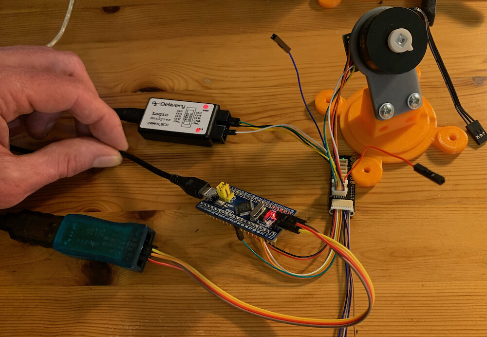
Hey, I did a quick test setup:
- SimpleFOC 2.1.1 master branch (current normal version of the library)
- BluePill STM32F103C8
- AS5047P sensor
- PlatformIO, STM32 support v13.0
- Motor not connected, just the sensor
I can report the following:
It actually works out of the box, with no modifications to MagneticSensorSPI.cpp.
The resulting speed is too fast for my crappy logic analyser, the oscilloscope shows the clock line is at 9MHz:
That makes sense since we set the pre-scaler to 8, and 72MHz system clock / 8 = 9MHz SPI clock in this case.
Surprisingly, this is working fine even via the SPI hub and all the cables:
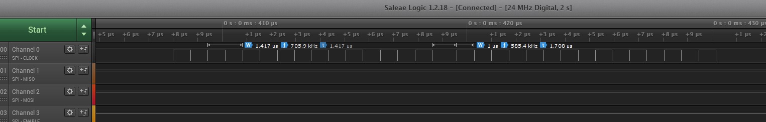
With my suggested modifications to MagneticSensorSPI, the picture changes to:
So now we don’t set the pre-scaler, but rather allow beginTransaction() to apply the clock_speed as specified in the settings object.
So we get 1MHz SPI clock, as specified in the settings.
To me this confirms the following:
-
the standard settings kind of work with STM32. But the bus speed does not get set, via the settings, resulting in a MCU-dependent default bus speed via the pre-scaler setting of 8, which is often much too high. I’m surprised my setup works at 9MHz, and I think if there were a BLDC driver and motor running chances are it wouldn’t work well any more.
-
the current code prevents the bus speed from being set correctly on STM32, so as a result, many people will have trouble with the current code under STM32 (as we see in this thread).
So I will fix the code for the next release of SimpleFOC, and in the meantime I encourage users to modify MagneticSensorSPI.cpp as described above.
A separate question:
Why do you see 705.9 KHz?
- I guess there is some inaccuracies in the timing estimation - the logic analyser, even at 24MHz, doesn’t hit the transitions directly.
- I think the SPI speed you set via clock_speed is the time for one on or off pulse, not the time from on-pulse to on-pulse. So the SPI clock rate is half the clock speed. I think. Its a bit unclear from the docs.
For reference, here is the code I was running:
#include "Arduino.h"
#include "SPI.h"
#include "SimpleFOC.h"


MagneticSensorSPIConfig_s AS5047P_SPI = {
  .spi_mode = SPI_MODE1,
  .clock_speed = 1000000,
 .bit_resolution = 14,
 .angle_register = 0x3FFF,
 .data_start_bit = 13,
 .command_rw_bit = 14,
 .command_parity_bit = 15
};
#define nCS_PIN PA15
MagneticSensorSPI sensor(AS5047P_SPI, nCS_PIN);


void setup() {
    Serial.begin(115200);
    while (!Serial);
    sensor.init();
}

void loop() {
    delay(100);
    Serial.println(sensor.getAngle(), 4);
}
And here is the modified MagneticSensor.cpp:
#ifndef TARGET_RP2040

#include "MagneticSensorSPI.h"

/** Typical configuration for the 14bit AMS AS5147 magnetic sensor over SPI interface */
MagneticSensorSPIConfig_s AS5147_SPI = {
  .spi_mode = SPI_MODE1,
  .clock_speed = 1000000,
  .bit_resolution = 14,
  .angle_register = 0x3FFF,
  .data_start_bit = 13,
  .command_rw_bit = 14,
  .command_parity_bit = 15
};
// AS5048 and AS5047 are the same as AS5147
MagneticSensorSPIConfig_s AS5048_SPI = AS5147_SPI;
MagneticSensorSPIConfig_s AS5047_SPI = AS5147_SPI;

/** Typical configuration for the 14bit MonolithicPower MA730 magnetic sensor over SPI interface */
MagneticSensorSPIConfig_s MA730_SPI = {
  .spi_mode = SPI_MODE0,
  .clock_speed = 1000000,
  .bit_resolution = 14,
  .angle_register = 0x0000,
  .data_start_bit = 15,
  .command_rw_bit = 0,  // not required
  .command_parity_bit = 0 // parity not implemented
};


// MagneticSensorSPI(int cs, float _bit_resolution, int _angle_register)
//  cs              - SPI chip select pin
//  _bit_resolution   sensor resolution bit number
// _angle_register  - (optional) angle read register - default 0x3FFF
MagneticSensorSPI::MagneticSensorSPI(int cs, float _bit_resolution, int _angle_register){

  chip_select_pin = cs;
  // angle read register of the magnetic sensor
  angle_register = _angle_register ? _angle_register : DEF_ANGLE_REGISTER;
  // register maximum value (counts per revolution)
  cpr = pow(2,_bit_resolution);
  spi_mode = SPI_MODE1;
  clock_speed = 1000000;
  bit_resolution = _bit_resolution;

  command_parity_bit = 15; // for backwards compatibilty
  command_rw_bit = 14; // for backwards compatibilty
  data_start_bit = 13; // for backwards compatibilty
}

MagneticSensorSPI::MagneticSensorSPI(MagneticSensorSPIConfig_s config, int cs){
  chip_select_pin = cs;
  // angle read register of the magnetic sensor
  angle_register = config.angle_register ? config.angle_register : DEF_ANGLE_REGISTER;
  // register maximum value (counts per revolution)
  cpr = pow(2, config.bit_resolution);
  spi_mode = config.spi_mode;
  clock_speed = config.clock_speed;
  bit_resolution = config.bit_resolution;

  command_parity_bit = config.command_parity_bit; // for backwards compatibilty
  command_rw_bit = config.command_rw_bit; // for backwards compatibilty
  data_start_bit = config.data_start_bit; // for backwards compatibilty
}

void MagneticSensorSPI::init(SPIClass* _spi){

  spi = _spi;

	// 1MHz clock (AMS should be able to accept up to 10MHz)
	settings = SPISettings(clock_speed, MSBFIRST, spi_mode);

	//setup pins
	pinMode(chip_select_pin, OUTPUT);

	//SPI has an internal SPI-device counter, it is possible to call "begin()" from different devices
	spi->begin();
#ifndef ESP_H // if not ESP32 board
	spi->setBitOrder(MSBFIRST); // Set the SPI_1 bit order
	spi->setDataMode(spi_mode) ;
//	spi->setClockDivider(SPI_CLOCK_DIV8);
#endif

	digitalWrite(chip_select_pin, HIGH);
	// velocity calculation init
	angle_prev = 0;
	velocity_calc_timestamp = _micros();

	// full rotations tracking number
	full_rotation_offset = 0;
	angle_data_prev = getRawCount();
}

//  Shaft angle calculation
//  angle is in radians [rad]
float MagneticSensorSPI::getAngle(){
  // raw data from the sensor
  float angle_data = getRawCount();

  // tracking the number of rotations
  // in order to expand angle range form [0,2PI]
  // to basically infinity
  float d_angle = angle_data - angle_data_prev;
  // if overflow happened track it as full rotation
  if(abs(d_angle) > (0.8*cpr) ) full_rotation_offset += d_angle > 0 ? -_2PI : _2PI;
  // save the current angle value for the next steps
  // in order to know if overflow happened
  angle_data_prev = angle_data;

  // return the full angle
  // (number of full rotations)*2PI + current sensor angle
  return full_rotation_offset + ( angle_data / (float)cpr) * _2PI;
}

// Shaft velocity calculation
float MagneticSensorSPI::getVelocity(){
  // calculate sample time
  unsigned long now_us = _micros();
  float Ts = (now_us - velocity_calc_timestamp)*1e-6;
  // quick fix for strange cases (micros overflow)
  if(Ts <= 0 || Ts > 0.5) Ts = 1e-3;

  // current angle
  float angle_c = getAngle();
  // velocity calculation
  float vel = (angle_c - angle_prev)/Ts;

  // save variables for future pass
  angle_prev = angle_c;
  velocity_calc_timestamp = now_us;
  return vel;
}


// function reading the raw counter of the magnetic sensor
int MagneticSensorSPI::getRawCount(){
	return (int)MagneticSensorSPI::read(angle_register);
}

// SPI functions
/**
 * Utility function used to calculate even parity of word
 */
byte MagneticSensorSPI::spiCalcEvenParity(word value){
	byte cnt = 0;
	byte i;

	for (i = 0; i < 16; i++)
	{
		if (value & 0x1) cnt++;
		value >>= 1;
	}
	return cnt & 0x1;
}

  /*
  * Read a register from the sensor
  * Takes the address of the register as a 16 bit word
  * Returns the value of the register
  */
word MagneticSensorSPI::read(word angle_register){

  word command = angle_register;

  if (command_rw_bit > 0) {
    command = angle_register | (1 < 0) {
   	//Add a parity bit on the the MSB
  	command |= ((word)spiCalcEvenParity(command) < < command_parity_bit); // space between < symbols should be removed! It is inserted for the forum
  }

//#if !defined(_STM32_DEF_) // if not stm chips
  //SPI - begin transaction
  spi->beginTransaction(settings);
//#endif

  //Send the command
  digitalWrite(chip_select_pin, LOW);
  digitalWrite(chip_select_pin, LOW);
  spi->transfer16(command);
  digitalWrite(chip_select_pin,HIGH);
  digitalWrite(chip_select_pin,HIGH);

#if defined( ESP_H ) // if ESP32 board
  delayMicroseconds(50);
#else
  delayMicroseconds(10);
#endif

  //Now read the response
  digitalWrite(chip_select_pin, LOW);
  digitalWrite(chip_select_pin, LOW);
  word register_value = spi->transfer16(0x00);
  digitalWrite(chip_select_pin, HIGH);
  digitalWrite(chip_select_pin,HIGH);

//#if !defined(_STM32_DEF_) // if not stm chips
  //SPI - end transaction
  spi->endTransaction();
//#endif

  register_value = register_value >> (1 + data_start_bit - bit_resolution);  //this should shift data to the rightmost bits of the word

  const static word data_mask = 0xFFFF >> (16 - bit_resolution);

	return register_value & data_mask;  // Return the data, stripping the non data (e.g parity) bits
}

/**
 * Closes the SPI connection
 * SPI has an internal SPI-device counter, for each init()-call the close() function must be called exactly 1 time
 */
void MagneticSensorSPI::close(){
	spi->end();
}


#endif