Segway minirobot сhinese version

Give me a hint, please. There is a board from a Segway minirobot, a Chinese version. The board is very similar to the board of a hoverboard, but I can’t understand some things.
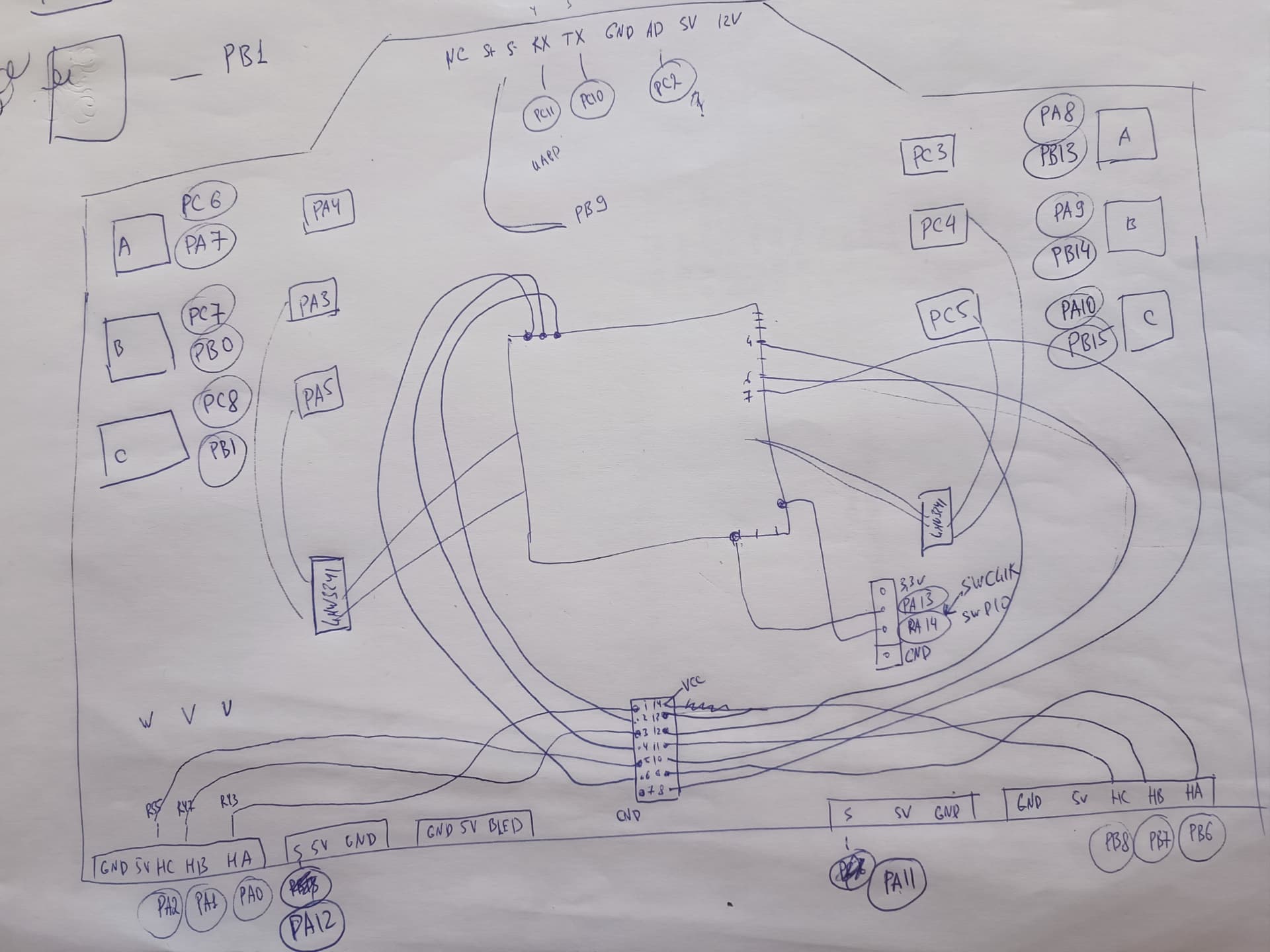
Mcu GD32F103RCT6
There are two operational amplifiers LMW324I, apparently for measuring current, but I don’t understand how to set shunt_resistor and gain for LowsideCurrentSense.
The hall sensors are connected via a microcircuit similar to an operational amplifier, unfortunately I can’t make out the markings.
I didn’t find if there is a voltage measurement like on the board of a hoverboard, because there are only 2 operational amplifiers.

I tried to run it on SimpleFOS. I flashed it like STM32 and checked it on the motor of hoverboard (15pp).

  1. Hall sensors work fine, checked manually by turning the motor, one revolution shows correctly.
  2. Then I started the velocity openloop, the motor rotated if I set the target to 3, if I set more than 5 the motor only vibrates, if less than 3 it does not rotate.
  3. Then I tested with the torque control mode, the motor starts to rotate if I set 2v, it sets a maximum of 500 rpm at 10v, does not accelerate more.
  4. I could not check with the current sensor, the processor is flashed, but at the moment current_sense.init() everything freezes, these are apparently artifacts where GD32?
    I wanted to check on the firmware GitHub - EFeru/hoverboard-firmware-hack-FOC: With Field Oriented Control (FOC) but I did not find a voltage sensor on the board.
    Please give me some hints where to dig, maybe someone has encountered such boards?

This is the pinout that I was able to figure out.

Hi,
I might not be able to answer all questions but here are few comments:

  • the hoverboard FOC firmware uses same exact code for ST32F103 and GD32F103 chips and it works because the GD32 is a really close clone. But there are still difference, I am not sure if SimpleFOC would need some adjustments
  • keep in mind SimpleFOC doesn’t support Dual FOC on STM32 at the moment, so initializing 2 current sense won’t work

I would first make sure torque/voltage mode works well, we can help if you share your code.
You should also use the smoothing sensor, it will reduce noise and is needed later for FOC.
Then you will be able to try FOC but on a single motor for now.

Thanks for the reply
Yes, I’m trying to run with only one motor
Tried the smoothing sensor, but it seems nothing changed.
Currently the status is as follows
1v motor does not move
2-8v spins, picks up speed, but there is noise, the noise is like a bearing has fallen apart
9v noise increases greatly
My code

#include <Arduino.h>
#include <SimpleFOC.h>
#include <SimpleFOCDrivers.h>
#include <encoders/smoothing/SmoothingSensor.h>
#include "config.h"

HallSensor sensor = HallSensor(BLDC_HALL_A_PIN, BLDC_HALL_B_PIN, BLDC_HALL_C_PIN, BLDC_POLE_PAIRS);

void doA()  { sensor.handleA(); } 
void doB()  { sensor.handleB(); }
void doC()  { sensor.handleC(); }

BLDCMotor motor = BLDCMotor(BLDC_POLE_PAIRS); // int pp,  float R = NOT_SET [Ohm], float KV = NOT_SET [rpm/V], float L = NOT_SET [H]

BLDCDriver6PWM driver = BLDCDriver6PWM( BLDC_A_H_PIN,BLDC_A_L_PIN,  BLDC_B_H_PIN,BLDC_B_L_PIN,  BLDC_C_H_PIN,BLDC_C_L_PIN );

// shunt resistor value , gain value,  pins phase A,B,C
LowsideCurrentSense current_sense = LowsideCurrentSense(BLDC_CUR_Rds, BLDC_CUR_Gain, BLDC_CUR_A_PIN, BLDC_CUR_B_PIN, BLDC_CUR_C_PIN);

SmoothingSensor smooth = SmoothingSensor(sensor, motor);

HardwareSerial SerialMy(RX_PIN, TX_PIN);

Commander commander = Commander(SerialMy, '\n', true);
void doMotor(char* cmd) { commander.motor(&motor, cmd); }

void setup() {
  SerialMy.begin(115200);
  SimpleFOCDebug::enable(&SerialMy);

  pinMode(SELF_HOLD_PIN, OUTPUT);
  pinMode(BUTTON_PIN, INPUT);
  digitalWrite(SELF_HOLD_PIN, HIGH); 

  sensor.pullup = Pullup::USE_EXTERN;
  sensor.enableInterrupts(doA, doB, doC);
  sensor.init();

  //motor.linkSensor(&sensor);
  motor.linkSensor(&smooth);

  driver.voltage_power_supply = 3.6 * BAT_CELLS;
  driver.voltage_limit = driver.voltage_power_supply/2;
  driver.pwm_frequency = 16000;
  driver.dead_zone = 0.05f;
  
  if (!driver.init()){
    SerialMy.println("Driver init failed!");
    return;
  }
  SerialMy.println("Driver init OK!");

  // link driver
  motor.linkDriver(&driver);
  
  //link current sense and the driver
  // current_sense.linkDriver(&driver);

  // current sense init
  // if(!current_sense.init()){
  //     SerialMy.println("Current sense init failed!");
  //     return;
  // }
  // SerialMy.println("Current sense init OK!");

  // // link the current sense to the motor
  // motor.linkCurrentSense(&current_sense);
  
  motor.voltage_sensor_align  = 3; // default 3V

  //motor phase resistance [Ohms]
  motor.phase_resistance = 1.2; // Ohms - default not set
  // motor KV rating [rpm/V] 15.98 rpmV * 30/pi = 152 +50% = 230
  //motor.KV_rating = 230; 
  //motor.phase_inductance = 0.00036858;


  motor.current_limit = 2;
  //driver.voltage_limit = 2;

  
  motor.foc_modulation        = FOCModulationType::Trapezoid_120;
  motor.torque_controller     = TorqueControlType::voltage;
  motor.controller                 = MotionControlType::torque;

  if(!motor.init()){
    SerialMy.println("Motor init failed!");
    return;
  }

  if (!motor.initFOC()) {
    SerialMy.println("Motor initFoc failed!");
    return;
  }

  motor.target = 0; 
  
  commander.add('M', doMotor, "Motor");
  
  SerialMy.println("Motor ready.");
  _delay(1000);  

}

void loop() {
  // sensor.update();
  // SerialMy.print(sensor.getAngle());
  // SerialMy.print("\t");
  // SerialMy.println(sensor.getVelocity());
  // _delay(200); 

  if (motor.enabled) {
    motor.loopFOC();
    motor.move();
    commander.run();
  } else {
    SerialMy.print(".");
  }


  if (digitalRead(BUTTON_PIN) == HIGH) {
    while (digitalRead(BUTTON_PIN) == HIGH) { 
    }
    digitalWrite(SELF_HOLD_PIN, LOW); 
  }

}

Trapezoidal will sure be noisy, and the smoothing sensor will not help in this case.
You need to use SinePWM or SpaceVectorPWM with the smoothing sensor.

With hall sensors, smoothing sensor needs a specific setting:

smooth.phase_correction = -_PI_6;

I wouldn’t do this for now, it will do a current estimation and the value looks wrong:

motor.phase_resistance = 1.2;

motor.foc_modulation = FOCModulationType::SinePWM;
smooth.phase_correction = -_PI_6;
//motor.phase_resistance = 1.2;

Thanks, that helped
Now the motor sound is almost perfect up to about 340 rpm, if the revs are higher, the bad sound returns. At the same time, there is still high-frequency vibration at all revs.

Let me ask a few more questions

  1. Is there any experience with the gyro scooter motor on velocity_openloop, according to the instructions, we need to check the pp? but pp we know for sure that it is 15. I could not run it on velocity_openloop, only two mosfets burned out (the other one did not have a limiting power supply)
  2. Considering that SmoothingSensor helped, can we conclude that the problem is only in positioning? Should I try to further select phase_correction? I suppose somewhere in GitHub - EFeru/hoverboard-firmware-hack-FOC: With Field Oriented Control (FOC) there are already similar coefficients
  3. Unfortunately I still can’t check LowsideCurrentSense, the board hangs, can you give me some advice on where to go?

For higher speed, the inductance needs to be compensated:

  • this is achieved with lag compensation in voltage mode if you know the correct phase resistance, phase inductance and KV
  • or with FOC when current sense works, without any motor parameters

About your questions:

  1. PP check in SimpleFOC won’t work with hall sensors, it needs an encoder. But 15 is correct for a hoverboard motor. It’s important to set up a much lower voltage for velocity_openloop than the one used for close loop.
  2. What SmoothingSensor does is interpolation of the angle, it’s needed because Hall Sensors provides and update only every 4 mechanical degrees. The hoverboard FOC firmware starts without interpolation when speed is low or direction change, and then uses the interpolation when speed is high enough.
  3. It’s hard to help here without details. Please share exactly where it hangs if you can use a debugger. Using the SIMPLEFOC_STM32_DEBUG build flag could also help get more details from the serial output. From your code we cannot see what parameters you are using to initialize current sense.

This is my output before enabling current sense.

18:46:24.478 -> TIM8-CH1 TIM8-CH1N TIM8-CH2CH1 TIM8-CH1N TIM8-CH2 TIM3-CH3 TIM8-CH3 TIM8-CH3N score: -6
18:46:24.516 -> TIM8-CH1 TIM8-CH1N TIM8-CH2 TIM3-CH3 TIM3-CH3 TIM1-CH3N score: -4
18:46:24.562 -> TIM8-CH1 TIM8-CH1N TIM8-CH2 TIM3-CH3 TIM3-CH3 TIM3-CH4 score: -4
18:46:24.562 -> TIM8-CH1 TIM8-CH1N TIM8-CH2 TIM3-CH3 TIM3-CH3CH2N TIM3-CH3 TIM1-CH3N score: -6
18:46:24.562 -> TIM8-CH1 TIM8-CH1N TIM8-CH2 TIM8-CH2N TIM3-CH3 TIM3-CH4 score: -6
18:46:24.594 -> TIM8-CH1 TIM8-CH1N TIM8-CH2 TIM8-CH2N TIM3-CH3 TIM3-CH4 score: -6
18:46:24.640 -> TIM8-CH1 TIM8-CH1N TIM8-CH2 TIM8-CH2N TIM3-CH3 TIM8-CH3N score: -6
18:46:24.640 -> TIMore: 1
18:46:24.686 -> STM32-DRV: best: TIM8-CH1 TIM8-CH1N TIM8-CH2 TIM8-CH2N TIM8-CH3 TIM8-CH3N score: 1
18:46:24.686 -> STM32-DRV: Syncronising timers! Timer no. 1
18:46:24.686 -> STM32-DRV: Restarting timer 8
18:46:24.719 -> Driver init OK!
18:46:24.766 -> MOT: Monitor enabled!
18:46:24.766 -> MOT: Init
18:46:25.108 -> MOT: Enable driver.
18:46:25.951 -> MOT: Align sensor.
18:46:28.486 -> MOT: sensor_direction==CW
18:46:28.526 -> MOT: PP check: fail - estimated pp: 18.00
18:46:28.572 -> MOT: Zero elec. angle: 3.14
18:46:28.705 -> MOT: No current sense.
18:46:28.705 -> MOT: Ready.
18:46:28.743 -> Motor ready.

My platformio ini

debug_tool = stlink
upload_protocol = stlink
platform = ststm32
board = genericSTM32F103RC
framework = arduino
lib_archive = false
lib_deps = 
	askuric/Simple FOC@^2.3.4
	simplefoc/SimpleFOCDrivers@^1.0.8
monitor_speed = 115200
build_flags = -D $PIOENV
	-D SIMPLEFOC_PWM_LOWSIDE_ACTIVE_HIGH=false
	-D SIMPLEFOC_STM32_DEBUG=1

I uncommented the code above current_sense and I get this

18:52:01.070 -> TIM8-CH1 TIM8-CH1N TIM3-CH2 TIM8-CH2N TIM8-CH3 TIM3-CH4 score: -6
18:52:01.113 -> TIM8-CH1 TIM8-CH1N TIM3-CH2 TIM8-CH2N TIM8-CH3 TIM8-CH3N score: -6
18:52:01.113 -> TIM8-CH1 TIM score: -6
18:52:01.148 -> TIM8-CH1 TIM8-CH1N TIM8-CH2 TIM3-CH3 TIM3-CH3 TIM1-CH3N score: -4
18:52:01.194 -> TIM8-CH1 TIM8-CH1N TIM8-CH2 TIM3-CH3 TIM3-CH3 TIM3-CH4 score: -4
18:52:01.238 -> TIM8-CH1 TIM8-CH1N TIM8-CH2 T TIM8-CH1N TIM8-CH2 TIM3-CH3 TIM8-CH3 TIM3-CH4 score: -6
18:52:01.238 -> TIM8-CH1 TIM8-CH1N TIM8-CH2 TIM3-CH3 TIM8-CH3 TIM3-CH4 score: -6
18:52:01.238 -> TIM8-CH1 TIM8-CH1N TIM8-CH2 TIM3-CH3 TIM8-CH3 TIM8-CH3N score: -6
18:52:01.271 -> TIM8-CH1 TIM8-CH1N TIM8-CH2 TIM8-CH2N TIM3-CH3 TICH3 TIM3-CH4 score: -6
18:52:01.306 -> TIM8-CH1 TIM8-CH1N TIM8-CH2 TIM8-CH2N TIM3-CH3 TIM8-CH3N score: -6
18:52:01.306 -> TIM8-CH1 TIM8-CH1N TIM8-CH2 TIM8-CH1 TIM8-CH1N TIM8-CH2 TIM8-CH2N TIM8-CH3 TIM8-CH3N score: 1
18:52:02.323 -> STM32-DRV: Syncronising timers! T

My pins

    #define BLDC_HALL_A_PIN PA0	
    #define BLDC_HALL_B_PIN PA1	
    #define BLDC_HALL_C_PIN PA2	

    #define BLDC_A_H_PIN PC6		
    #define BLDC_A_L_PIN PA7

    #define BLDC_B_H_PIN PC7		
    #define BLDC_B_L_PIN PB0

    #define BLDC_C_H_PIN PC8
    #define BLDC_C_L_PIN PB1

    #define BLDC_CUR_A_PIN PA4
    #define BLDC_CUR_B_PIN PA3
    #define BLDC_CUR_C_PIN PA5

Thanks for any tips

And one more general question. Were you able to configure SimpleFoс so that it would work on the hoverboard board no worse than EFeru/hoverboard-firmware-hack-FOC?

Try the other side maybe. TIM8 cannot trigger injected ADC (code).
I am not sure why it would fail like this though.

The hoverboard FOC firmware works very well because the implementation is fast ( FOC control loop runs at 16khz with 2 motors thanks to fix-point math) and because it’s tuned for hoverboard motors already.

But it’s not easy to adapt and is not maintained anymore. So it won’t get things like:

  • encoder support
  • position control
  • sensorless

With good tuning, it should run well with SimpleFOC also.
My only doubt is that SimpleFOC is much slower on STM32F1, but I am not sure if it can be an issue on those motors.

Hi. I tried it on another hoverboard board, which is fully tested on the EFeru/hoverboard-firmware-hack-FOC firmware and works well, has the same Mcu GD32F103RCT6. I haven’t managed to achieve good engine performance yet, but at least it spins in voltage mode.

Regarding current sense, if you select the left side, the firmware does not start with current sense, the error is the same as on the first board, something TIM8
If you start the right side (TIM1), the firmware starts and gives an error

15:12:49.304 -> MOT: sensor_direction==CW
15:12:49.337 -> MOT: PP check: OK!
15:12:50.024 -> MOT: Zero elec. angle: 0.00
15:12:50.254 -> MOT: Align current sense.
15:12:51.323 -> CS: Switch A-(C)NC
15:12:52.423 -> CS: Err B - all currents same magnitude!
15:12:52.464 -> MOT: Align error!
15:12:52.464 -> MOT: Init FOC failed.
15:12:52.499 -> Motor initFoc failed!

I tried playing with shunt_resistor and gain did not give any results.
Please give me some tips?

What are the parameters you use for current sense ?

These

LowsideCurrentSense current_sense = LowsideCurrentSense(0.008, 50, PC4, PC5, _NC);

How about this:

LowsideCurrentSense current_sense = LowsideCurrentSense(0.008, -2.5, PC5, PC4, _NC);

The result is the same

This used to work for me, but there is a new current sense alignment procedure now, need to try when I have time.

I reread the documentation, moved the current_sense.init() code below motor.init() and it worked, apparently this is important for automatic alignment. Not at all obvious behavior, you can easily miss this moment.
And how to choose the right shunt_resistor, gain?

Hmmm that’s weird. We need to check this.

There is no shunt resistor for phase current on hoverboard controllers, the Mosfet RDSON is used as shunt. So you have to check the datasheet of your mosfets.

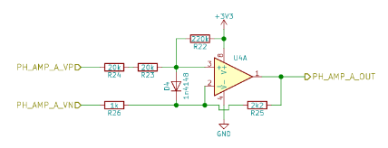
The gain has to be derived from the schematics, but I am really not an expert here:
image

Thank you very much for the tips
The most important thing is that the motor works in voltage mode without vibration and sounds.
What else can you pay attention to besides smooth.phase_correction = -_PI_6; to get rid of vibration and noise?
I also noticed at the moment that if I turn on the MotionControlType::angle mode, the motor immediately starts to rotate and does not stop even if I specify a target other than 0.