Update on SAMD: I have the configuration working in theory 
I spent some time on the weekend and yesterday working on it, and have code which (to me) looks ok, and also seems to work.
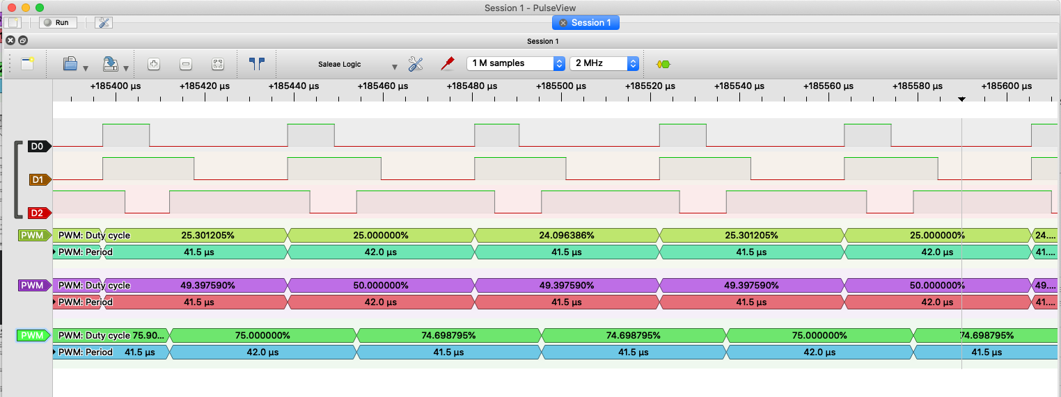
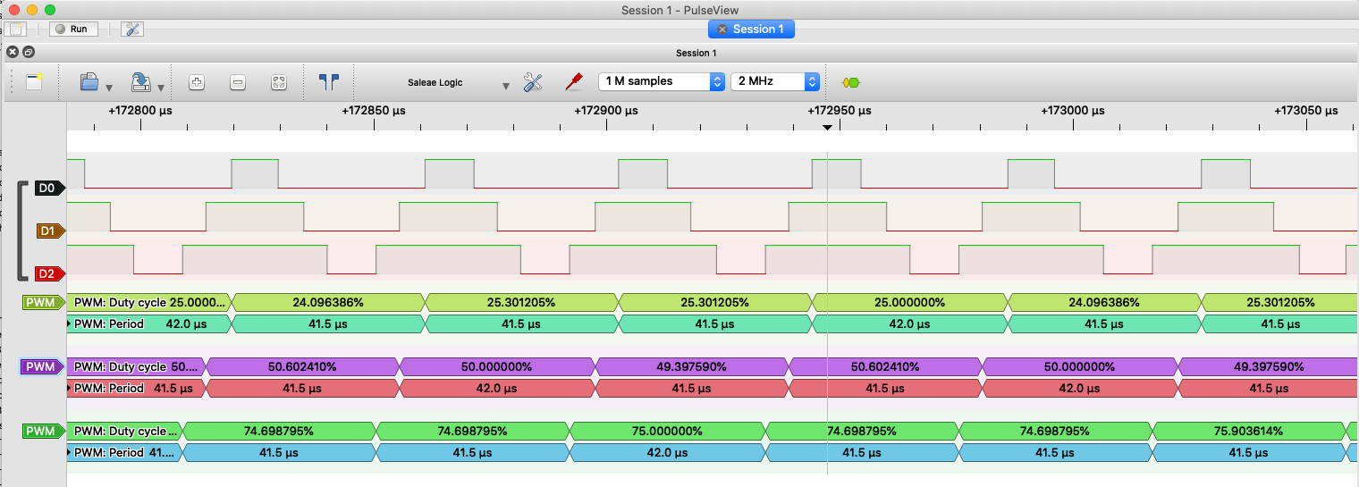
When I explicitly configure the TCCs, I get nice PWM signals and turning motors. If I leave it to the “auto-configuration”, then it doesn’t work…
The problem is the following:
SAMD isn’t very flexible regarding its timer outputs. Each of the MCUs pins is associated with zero, one or two timer-outputs (called WOs in SAMD-speak, and designated like TCC0/WO[2], meaning Timer 0, Output 2). Note that the different WOs are typically associated to more than one pin. Each timer has either 2 or 4 channels, but always twice as many WOs. The extra WOs can be used in certain modes (like dead-time insertion), but you can only have as many different PWM signals as the timer has channels, i.e. you can’t use all the WOs independently, only half.
To configure the PWM, we need to decide which of the associated timers to actually “attach” to the pin, since there could be up to 2 options, and the timers are not attached by default.
Ideally, all the pins for one simplefoc driver come from the same timer, but this is not always possible because of the choice of pins the user makes:
- pins could have no timers associated
- the pins could have only different timers associated
- the timers could already be in use
- the timer outputs could be “incompatible” - for example TCC0/WO[0] and TCC0/WO[4] are the same channel, and incompatible for 3-PWM
Note: all this gets even more complex if you’re trying to drive more than one motor, and unless we want major API changes we can’t do better than initialise the motors in some order, and hope that we don’t choose assignments that will make it impossible for a later motor to find a compatible setting.
So finding working combinations between 3 pins (or 6 pins) is a matter of testing different permutations of the 1 or 2 timers attached to the pins.
I’ve written the code that searches for working permutations, and this seems to work.
So what’s the problem? In order to make all this work we need a source of information about the pin to timer associations. Normally, this is provided in variant.cpp in the g_APinDescription array.
This array includes the port/PIN numbers, and the peripheral associations for peripherals E and F (which are the 2 timers that could be associated).
However, for all the boards I’ve looked at so far (MKR WiFi 1000, Adafruit Feather M0, Nano 33 IoT) the g_APinDescription array is just plain wrong. It incorrectly sets the pin attributes, and incorrectly sets the values for peripherals E and F.
The g_APinDescription disagrees with both the SAMD datasheet and (in the case of the Arduino boards) with the pinout diagrams provided for the boards.
I don’t fully understand how they can ship the software in that state, and the boards still work, but I guess the TCC units are advanced features that most people aren’t using, and the kind of auto-configuration we’re trying to do in SimpleFOC is probably not a very common use case.
So, I need a different source of truth for the g_APinDescription data.
Does anyone (@Gouldpa) have any ideas for this? I can’t so far find it in the SAMD specific headers either.
Otherwise, my approach will be to capture the information from the datasheet, indexed by PortPin since there is little variation in the timer to PortPin associations across the models. I looks like I will only have to capture 2 tables for SAMD21, I still have to check SAMD51.
Then I can use the PortPin information from g_APinDescription (which seems to be correct) to retrieve the timer associations from the chip-specific table.
I think this is better than trying to do it on a per board basis, since there are far more boards than SAMDs, and they all have the same PortPin configurations based on the chip they’re using.