SAMD support working

Sorry for the delay. Last week was unexpectedly very busy work wise, and I didn’t get back to SimpleFOC until this weekend.

I now have 6-PWM working, both in hardware mode and software…

Here’s where I’m at:

  • 6-PWM can only be supported on the TCC units. I can’t think of a practical way to make the much weaker TC units sync up sufficiently precisely to get workable dead-time insertion from software. If anyone has ideas for this, they’re welcome.
  • Hardware Dead-time-insersion can work if the high and the low pin are on the same TCC unit and channel, but different outputs (WOs).
  • Software Dead-time-insertion can work if the high and the low pin are on the same TCC unit but different channels.
  • Hardware and Software DTI have identical timings


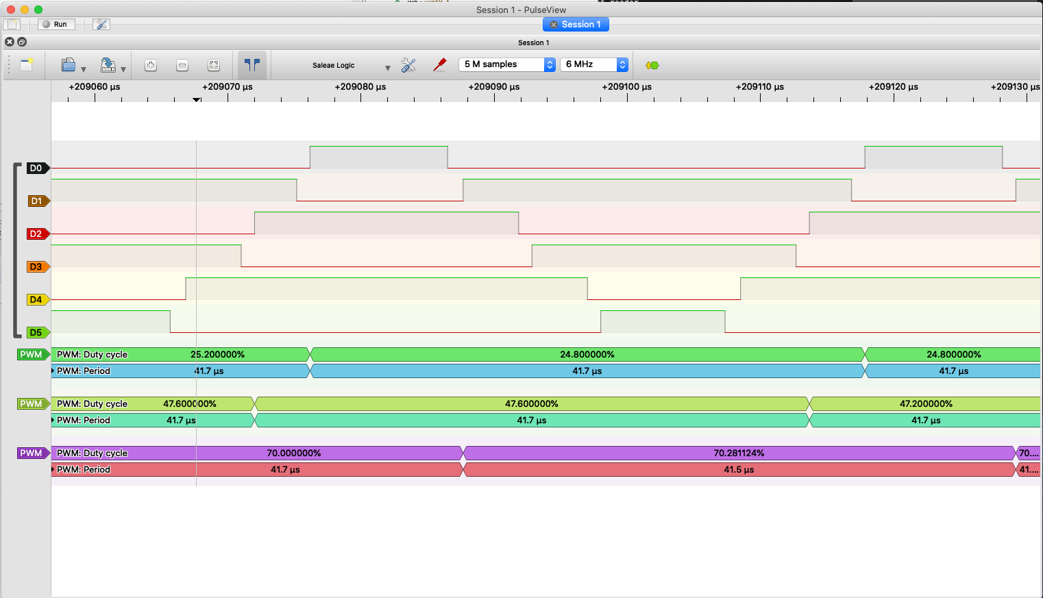
In this picture, D0=pinA_h, D1=pinA_l, D2=pinB_h, D3=pinB_l, D4=pinC_h and D5=pinC_l
pinA_h/pinA_l are using software-DTI, while the others are using hardware-DTI.

As usual, there is a small problem:
Hardware Dead-Time-Insertion needs to be set up at init-time, not during each update. So really I need the value of the “deadzone” parameter at init-time …

@Antun_Skuric is there any reason it is passed to the writeDutyCycle() methods rather than the configure() methods? Could we add it to the configure methods?

And could it be removed from the writeDutyCycle() methods? It seems to me that the value would be related to the MOSFETs used, and thus loop-invariant?

However, it seems SAMD would support separate values for High-Side and Low-Side dead-time (reflecting the fact that rise and fall times of the MOSFETs could be quite different)… would we want to support that?

Otherwise, I think I’m close to done. I still need to:

  • Clean up the code, remove debugs
  • See if I can get double buffering to work (so far no luck)
  • Test 6-PWM with a motor (so far only looking at the PWM waveforms)
  • Handle the dead-time issue mentionsd above
  • Write some docs

Hey @runger,
Those are some great news!

Those are exactly the requirements that we had to introduce as well. Same timer high-low side always and hardware 6pwm always the same timer pins. Well done.

The dead time is passed to the config and writepwm functions. And you can choose to use any one of those. It is necessary that it is passed to the write duty cycle because there are chips that have no dead time insertion and the only way to do it is to modify the duty cycle lengths directly and that is done in write duty cycle code. You can see Arduino implementation or stm32 software PWM version .

Actually for stms, software 6pwm uses dead_time in write function ad hardware sets it on the befinning in config, like in your case.

The stm and esp would support it too. But only in hardware mode (the only possible one for esp). I am not sure if this is worth the effort. It is an easy fix for later if there are people who are interested. :smiley:
For now I’d avoid adding additional parameters that do not apply to everyone. But maybe I’m wrong. :upside_down_face:

Doh! Somehow I didn’t see it. Late night coding… this topic is done. You can set the dead time via the parameter on a per-cycle basis for software-DTI, and during setup for hardware DTI.

I left some of the debug code in there, masked out by #define. Only the stuff that prints the TCC assignments for your pins, since I find that could be really useful to some people. The board level definitions are wrong, so unless you want to sit and match the Pin-Ports for each Pin against the SAMD Datasheet, enabling the debug code is a nice way to easily see that information on the serial monitor.

If you don’t #define SIMPLEFOC_SAMD_DEBUG, then nothing is written to Serial.

I added 2-PWM and 4-PWM initialisation code, based on the other implementations as example. I get PWM-outputs as expected, but really I can’t test it for lack of a stepper setup.

I still have to test the 6-PWM, see the DRV8316 thread for updates on that.

Even though the Stepper and 6-PWM code need more testing (on real motors!), and there is an open point for changing the duty cycle more smoothly, I think it could be ready for first public tests? Certainly SimpleFOC isn’t working out of the box for SAMD21 at all right now, and with the new code it would work with 3-PWM on most pin-combinations quite nicely, so a big improvement on the status quo.

In terms of IDE setups I have tested Sloeber (which is what I mainly use), Arduino IDE and Arduino Pro IDE. I haven’t yet tried PlatformIO.
In terms of board-environments I have tried with Arduino-SAMD, Adafruit-SAMD and Seeduino-SAMD.
In terms of boards, I’ve tried:
Arduino MKR1000
Arduino MKR1010
Arduino NANO 33 IoT
Seedunio Xaio
Adafruit Feather M0 Basic

I’ve tried SAMD51 and it doesn’t work yet. I will work on this and finishing the 6-PWM test next.

I think I might send a first pull request, if that is ok? @Antun_Skuric feel free to reject it and let me know what still needs to be changed to get it accepted…

Ok, I’ve updated the code:

  • it’s now against the dev branch, not master
  • I separated the (unrelated) OSC example
  • I tested hardware 6-pwm (using DRV8316EVM board)
  • I’ve sent a pull request against the dev branch

I think there are definitely still some rough edges, but I think it is ready for first tests in the wild…

2 Likes

Further updates on the SAMD support (currently in dev branch of simplefoc, but should be in the next release):

  • SAMD51 and SAME51 are now supported
  • PWM changes are now via the CCB / CCBUF registers for glitch-free phase-correct PWM

SAMD51/SAME51 have 3 timer peripherals on most pins, peripherals F & G are both for TCCs. They also have more TCCs than the SAMD21 so therefore (and unlike SAMD21) almost every pin has some TCC channel attached.
For this reason I haven’t bothered with TC units on SAMD51 - not really worth it since they are so much worse at motor control. People should just use Pins with TCC units, which is really almost all of them.

Still to do:

  • variable frequency of PWM
  • low side current sensing

At the moment it is fixed to 24kHz. But I have now figured out (I believe) how to use the clocks to get considerably faster clock inputs to the timers (96MHz instead of 48MHz on SAMD21, maybe even more on SAMD51).
So I will still implement variable PWM frequency (variable between lets say 20kHz and 50kHz should be possible).

I’ll report on progress here.

1 Like

Hello runger,

I’ve recently found the time to reproduce Paul Gould’s hackaday project (arduino) and then I found out about SimpleFOC and your recent efforts.

First, thank you and @Gouldpa very much for sharing all this.

My embedded programming skills are a bit rusty, but there was a time when I knew the avr2560 very very well. I’m completely new to BLDC but I’m very curious about the theory behind it. I’m mentionning that because I feel a bit challenged getting my samd21g dev + DRV8305 + AS5047 + 7 pole pairs bldc motor setup (already burnt one of those 3W resistors near the FETs on my DRV8305 eval board).

Where I’m at right now is that I got @Goulpa’s code “running” but I don’t know how to align the poles with the encoder, so the motor is just shaking and or locking (or burning fuses).

So yesterday I tried your code and I could reach the point of completing the initFoc() sequence.

motor.move() behaves in a weird manner, I tried ::velocity and ::angle controllers, and it’s not working as expected (in velocity mode, motor.move(0.1) will make the motor turn CW, then motor.move(0.2) will stop it, then motor.move(0.3) will make it turn CCW, and weird stuff like that)

I had quite a few issues with variant.cpp, I ended up printing the nice table at section 6 (p21) of https://cdn.sparkfun.com/datasheets/Dev/Arduino/Boards/Atmel-42181-SAM-D21_Datasheet.pdf.

I will try to fix it and upstream it to arduino’s git as soon as I’m out of the woods with my bldc setup.

I’m using platformio from vscode.

I will install kicad, learn how to use it, and make a schematic of my setup.

I just wanted to say that I have enough free time to push this till the end and, hopefully, help a bit along the way!

I’d very much like to port @Gouldpa’s DMA code for the adc. As soon as I link SimpleFOC’s current sensor, things go hectic.

More later…!

(edit here is the schematics, without the input sense)
outputname-1|690x488

Hey @malem, cool to hear you’re using it! The SAMD support in SimpleFOC is very new, and I’m not surprised there are problems. The current state of the release branch is not the one you want.

The dev branch of SimpleFOC contains important fixes to the PWM code, and it is now working well for me on SAMD21. I think we have plans to merge it and create a new release this weekend, but until then I would encourage you to use the dev branch of SimpleFOC.

High currents can be a problem when using a motor with low resistance. To prevent burning things, make sure you set driver.voltage_limit to a low value for your first tests. Maybe 0.5 or 0.2V, depending on the motor’s resistance. You can always raise it once you are confident things are working well.

I know what you mean about the pin descriptions in variant.cpp. The variant.cpp files for all the SAMD boards I have tested have all been incomplete and/or incorrect regarding the timer configurations. For this reason the SimpleFOC SAMD code contains its own table, based on the datasheet.

For the current sensing, I would also wait for one release - it is very actively under development right now. If you would want to help with the current sensing code, I would be most happy! Are you looking to support low-side, high-side or in-line current sensing?

Regards,

Richard

Hi Richard,

Thanks for the hints!

I updated to the dev branch, but now my encoder (which uses sercom5) doesn’t work anymore. I’ll have to debug why, it uses PA20, PA21 and PB02 (MISO, SCK, MOSI) and PA06 as CS, its a bit hackish, as you have to comment SERCOM5_Handler() in variant.cpp, but it’s the way I want it.

It must be a little detail somewhere. I’m using so many pins (6PWM + 3 input sense + 2 spi + nFault + EN_GATE…) I’m must be stepping in my shoelaces

Hey, I know what you mean! Based on my own experience and many problems I had I can only recommend taking it one step at a time - you know, first get the motor spinning open-loop, then add the sensor and do closed loop, and finally add current sensing… otherwise there are just so many variables it becomes really hard to keep an overview.

If the dev branch is not working well for you on SAMD21, then that is something I’d like to investigate with you, if you have the patience. For me it is working well. SAMD21 is not the fastest MCU, but I’m getting smooth motion and up to 70rad/s (not super-fast, but enough for many applications) on a 11 pole-pair gimbal motor.

Here is my setup:

  • I usually compile using Sloeber but I’ve also used Arduino IDE and PlatformIO
  • I’m using the Arduino SAMD support v1.8.11
  • In terms of SAMD21 have tested the Nano33 IoT, MKR1010 WiFi, and the MKR1000 (also the Feather M0 Express, but not recently on the dev branch)
  • I’m using the AS5048A SPI magnetic sensor, very similar to your AS5047.
  • I’m mostly using driver boards based on the DRV8316 to test it
  • I’m currently mostly using the EMAX GB4008 gimbal motor to test

A couple of questions:

  • are all the PWM pins on the same TCC unit, and are the High/Low outputs of the same phase on the same channel, but complementary output #s (WOs)? There’s only certain pin-combinations that will get you hardware 6-PWM support. The code currently prints the configuration it finds as you initialise the driver.
  • I’m using GCLK4 and the DFLL48M at the moment. If you were changing the settings on those it would not work well… (I’m planning to change the code to use the FDPLL96M at 96MHz in the near future though. That should enable you to vary the PWM frequency between about 20kHz to 48kHz - currently it is fixed at 24kHz)

All the best,

Richard

Hey,

Of course I have the patience, I won’t give up. Right now, suspect number one is this other modification to variant.cpp I haven’t told you about:

#define ENC_SPI_MISO 44 //29 D6 PA20 ser5:2 SER

#define ENC_SPI_SCK 45 // 30 D7 PA21 ser5:3 SER

#define ENC_SPI_MOSI 46 //47 A5 PB02 ser5:0 ALT

#define ENC_CS 42 // D8 PA06

SPIClass ENC_SPI_5 (&sercom5, ENC_SPI_MISO,  ENC_SPI_SCK,  ENC_SPI_MOSI, SPI_PAD_0_SCK_3, SERCOM_RX_PAD_2); 

MagneticSensorSPI sensor(AS5047_SPI, ENC_CS);
[...] in setup()
sensor.init(&ENC_SPI_5);
[....]
... in varient.cpp's g_APinDescription[] I added:
  // 44-47 - Alternate sercom 5
  { PORTA, 20, PIO_SERCOM, PIN_ATTR_NONE, No_ADC_Channel, NOT_ON_PWM, NOT_ON_TIMER, EXTERNAL_INT_NONE }, // D6/MISO: SERCOM5/PAD[2]
  { PORTA, 21, PIO_SERCOM, PIN_ATTR_NONE, No_ADC_Channel, NOT_ON_PWM, NOT_ON_TIMER, EXTERNAL_INT_NONE }, // D7/SCK: SERCOM5/PAD[3]
  { PORTB, 02, PIO_SERCOM_ALT, PIN_ATTR_NONE, No_ADC_Channel, NOT_ON_PWM, NOT_ON_TIMER, EXTERNAL_INT_NONE }, // A5/MOSI: SERCOM5/PAD[0]

I suspect something you did in your WO_associations lead to two incompatble hacks, but I don’t have a clue yet.

Right now I only have the sensor runing (w/o success), no motor, no driver, nothing. I have another code where I can attest the encoder is working (so it’s not hardware).

I have a few minutes to dig before I but my little monster to bed… digging

[ok forget it, the same behavior appears in the master branch too]

Wow, that is so weird. I have both spi read function in the same binary. The “legacy” one works (the 5306 -/+ value is right, it moves correctly when I move the motor) as long as I don’t call sensor.getAngle().

  SerialUSB.print(i);
  SerialUSB.print(": raw: ");
  SerialUSB.print(Serial5_Transmit(2, true));

  if(i%10 < 5)
  {
    SerialUSB.print("angle: ");
    SerialUSB.print(sensor.getAngle());
  }
  i++;
  SerialUSB.print("              \r\n");
Sensor ready
0: raw: 5308angle: 0.00              
1: raw: 0angle: 0.00              
2: raw: 0angle: 0.00              
3: raw: 0angle: 0.00              
4: raw: 0angle: 0.00              
5: raw: 0              
6: raw: 5306              
7: raw: 5307              
8: raw: 5305              
9: raw: 5306              
10: raw: 5305angle: 0.00              
11: raw: 5305angle: 0.00              
12: raw: 0angle: 0.00              
13: raw: 0angle: 0.00              
14: raw: 0angle: 0.00              
15: raw: 0              
16: raw: 5307              
17: raw: 5304              
18: raw: 5307              
19: raw: 5307              
20: raw: 5306angle: 0.00              
21: raw: 5305angle: 0.00  

with Serial5_Transmit() beign defined by

uint16_t drv_data = 0;
byte spi5_txbuf[2] = {0x3F, 0xFF};

uint16_t Serial5_Transmit(int spi5_chars_to_send, char blocking)
{

  if (blocking && spi5_chars_to_send==2)
  {  
    digitalWrite(ENC_CS, LOW);
    digitalWrite(ENC_CS, LOW);
    SERCOM5->SPI.INTENSET.reg = 0x00;
    SERCOM5->SPI.DATA.reg = spi5_txbuf[0];
    while (SERCOM5->SPI.INTFLAG.bit.DRE == 0);
    SERCOM5->SPI.DATA.reg = spi5_txbuf[1];    
    while(SERCOM5->SPI.INTFLAG.bit.RXC == 0 ){}
    drv_data=(SERCOM5->SPI.DATA.reg)<<8;
    while(SERCOM5->SPI.INTFLAG.bit.RXC == 0 ){}
      //first byte read 4
    drv_data+=(SERCOM5->SPI.DATA.reg);

    digitalWrite(ENC_CS, HIGH);
    digitalWrite(ENC_CS, HIGH);
  }
  const static int bit_resolution = 14;
  // .angle_register = 0x3FFF,
  const static int data_start_bit = 13;
  // .command_rw_bit = 14,
  // .command_parity_bit = 15
  const static word data_mask = 0xFFFF >> (16 - bit_resolution);

  const static word max = 1 << bit_resolution;
  const static word half_max = max >> 1;
  drv_data = (drv_data >> (1 + data_start_bit - bit_resolution)) & data_mask;  //this should shift data to the rightmost bits of the word
  return drv_data;

}

That would be good to know, but honestly I don’t think so. That table is purely internal to the driver code, and can’t affect other code. It just contains the correct timer peripheral information from the datasheet.

A possible conflict would be more along the lines of trying to use the same pins, the same timer units or the same clocks for different purposes.

I would encourage you to comment out all the sensor and SPI code, and just test if the motor turns nicely in open-loop velocity mode. If this is the case, then the PWM and motor driver code is working, and any problems are coming from the SPI/Sensor level of things, or conflicts.
If the motor doesn’t turn well in open-loop, then we should find the reason for that and solve it first, because adding sensors on top of the not working motor will be very confusing, and will certainly not work.

I’ve never tried to use SPI via registers, so I don’t fully understand your code. But I seem to understand that you are doing 2x 8-bit transfers out and then 2x 8bit transfers in.
I don’t know enough about it, but intuitively I would have said the reads and writes need to be interleaved. Is there no way you can set it to use 16-bit transfers? That’s what the sensor actually wants.

The way the code is written, these things will affect each other. The AMS sensors return the response of the previous command on the input of the current command. So your getAngle() is actually receiving the result of your sercom5 calls, and your sercom5 call is receiving the results of the last getAngle call…
getAngle() solves this by actually doing 2x 16-bit transfers, to ensure it is reading a current angle value.

Do you have a logic analyser? It will really be a great help debugging self-written SPI code…

Regards from Vienna,

Richard

I totally agree to begin with the motor in open loop, I will do that.

I found out what caused the weird behaviour that with the spi port. It was an unhappy combination fo two hard to figure out problems.

First, when I moved to dev branch, I took the opportunity to place the project under the “/lib” folder, which platformio interpret as static libraries. I haven’t digged up why, but when I use “MagneticSensorSPI” from a static library, the spi ends up being clocked wrongly and the 4 byte exchange takes 400us instead of 75us, as measured with my 500MHz Logic Analyser (yes! I do have one!)

Then, I found out I had probably damaged my samd21d as nothing would behave normally this morining. I use one of samd’s internal pullup on the DRV8305 nFault pin, I wonder if it’s draining too much?

Or maybe it’s that second 3W resistor I burnt that caused some spike, anyway, I switched chips and now I’m back to square A.

I will do as you suggest, and have it run open-loop, and then I’ll dig into why the closed-loop fails.

I found a quick way to put the whole drv8305 register description table into code, that will help me debug warnings and faults from the DRV. I read the specsheet yesterday, I’m quite impressed with all this chip can do.

I will soon share my DRV8305 code.

I saw you debug code, it would be nice to allow one to use SerialUSB instead of Serial (I can do it by editing variant.cpp, right now), and also, no biggie, but “SIMPLEFOC_SAMD_DEBUG” is currently defined, which segfaults if you don’t have Serial set up.

To answer some of your previous questions, Here is my setup:

Motor: 5010-360kv, no idea what’s the internal resistance on this, my multimeter is too cheap to give me an accurate reading in that range (the test leads begin to impact precisiont I beleive)

The SPI code you saw was pulled from Paul Gould’s code, I will soon port it to SPIClass.

My PWM pinout is the following:

#define UH 3 // PA09 (TCC0/WO[1] or TCC1/WO[3]) [Edited, I wrote PB09’s specs first)
#define UL 5 // PA15 (TC3/WO[1] or TCC0/WO[5])
#define VH 10 // PA18(TC3/WO[0] or TCC0/WO[2])
#define VL 11 // PA16 (TCC2/WO[0] or TCC0/WO[6])
#define WH 12 // PA19 (TC3/WO[1] or TCC0/WO[3])
#define WL 13 // PA17 (TC6/WO[1] or TCC0/WO[5])

I copied this pin assignment from Paul Gould’s schematics. As I’m writing it, I begin to realize it might not be compatible with the constraints you wrote about. I’m reviewing this right now and will check with the Logic Analyser if everything seems dandy.
[edit: I enabled the debugging on SerialUsb, here’s what it says:]

Found configuration:
3 normal    TCC0-1[1]
5 alternate TCC0-1[5]
10 alternate TCC0-2[2]
11 alternate TCC0-2[6]
12 alternate TCC0-3[3]
13 alternate TCC0-3[7]
Attached pins...
Configured clock...
    Initialized TCC 0-1[1]
(Re-)Initialized TCC 0-2[2]
(Re-)Initialized TCC 0-3[3]
Configured TCCs...

I’m using GCLK4 and the DFLL48M at the moment. If you were changing the settings on those it would not work well… (I’m planning to change the code to use the FDPLL96M at 96MHz in the near future though. That should enable you to vary the PWM frequency between about 20kHz to 48kHz - currently it is fixed at 24kHz)

I haven’t touched anything there, I guess these are controlled with fuses?

I’m programming with the bootloader, I have a sagger on the way from china…

Gosh, it was a baaad day!

2 steps forwards, one step backwards they say…

Many, many thanks for your generous answers!

Who-hoo!

I have it working in closed loop, motor.controller = MotionControlType::torque;

Now I can begin digging seriously!

1 Like

I’m jealous! :smiley:

Yes, that should definately be fixed. I will think about the best way to do that, because IMHO the output is very useful at this stage of the driver’s development…

That’s a good configuration - I’m sure Paul would have gotten it right. The comment after the #define marking pin 13 as TCC0/WO[5] is incorrect in the comment I think - it should be TCC0/WO[7].
So that actually looks good.

No its all configurable on the fly… there’s a cool online tool at Atmel Start which you can use to play around with the clocks, timers and other peripherals to check your configurations. It exports code for Atmel Studio which is not much good for Arduino, but helps seeing the register setups one needs.

That’s awesome, man! Do you know what it was?

I would have thought it’s possibly more of a problem that it’s too weakly pulled up with the internal pull-up, the datasheet of the DRV8305 says to use 1k-10k external pull-ups. SAMD21 internal pull-up is 40k… but the DRV8305 also says to sink max 7mA. Either way, I don’t see a situation here that would be dangerous to either chip. At 3.3V (?) 40k would mean only 82µA if I haven’t confused myself about what the setup is here.

Have you seen our Drivers Repository? If you’re up for it I could (or you could if you want to do it yourself!) add the code there once it is working well?

Anyway, I’m really happy to hear you got it working!

Jealous about that Windoze-only piece of junk that forces me to fire my VM? no you’re not!
I was mentionning it is 500MHz so you know the measurements are accurate, not bragging about it!

But that was stupid, we’re in the us scale, not ns.

Anyway, frankly apart of having everything working togheter (AS5047 spi, DRV8305 spi, 6x PWM) the only thing I changed is the torque controller.

the velocity controller doesn’t work for me, or, most likely, I’m clueless as how to use it.

It will be a pleasure to contribute the 8305 driver as soon as it’s ready!

“Funny” thing, when I spin my motor too fast, the resistors on my DRV8305 board are glowing red. I ordered new ones.
Then board I’m using is an aliexpress boostxl knockoff board when I ordered the replacement, I noticed the guy put R070 resistance (you can actually see yourself on the picture)!

The correct value is R007, as per design-files

That explains why mine burnt!

Even funnier is the fact that the resistance still work after burning the black label.

Hey @runger

I have this commit

I don’t think it’s very elegant totally but it works for me understand if you have something nicer in mind

Hey, that looks great to me! Would you send a pull request? I’d be very happy to merge it.

Will do!
I will also send you the MR for my drv8305 drvier… I really went haywire with this one… got my arm pulled in the architectural blender. It consumes a LOT of flash because I kinda coded the whole specheet verbatim, lol. It was tolerably quick to do with column-edit mode.

My goal with it is to expose all settings to Commander, and later to my upcomming spin to SimpleFOCStudio

BTW, I’m about to include current sensing, what’s the status in dev (you were talking about improvements…)

Do you use DMA like Paul Gould did?

Hey Richard,

What are the baords that you’ve tested your samd51 implementation with?
I’d like to set them as example boards in the docs :smiley: