I’ve come across a paper describing how to implement 4th order s-curve motion planning. Let’s see how this math does on the G4.
I will attempt to make a new class for it, since the existing TrapezoidPlanner code will not suffice.
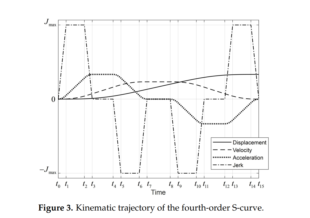
The move is divided into 15 segments. 3th order s-curve usually has 7 segments.
Feel free to join the effort
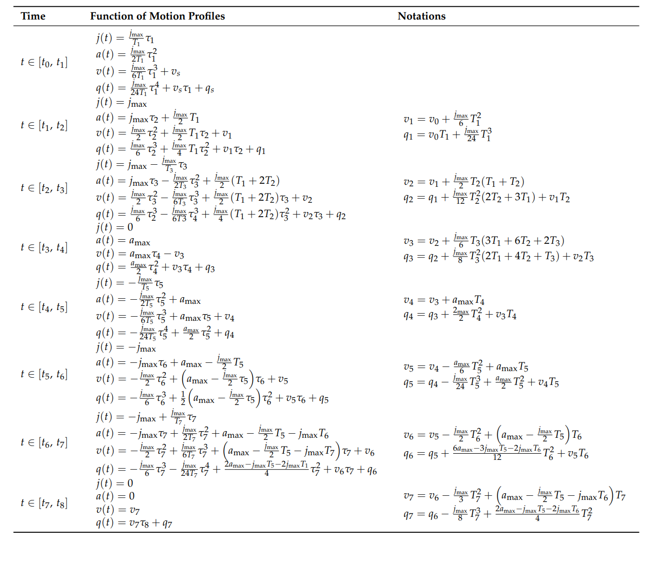
It’s all in the paper:
1 Like
Ok i think i cracked it!
Here are the transition times between the 15 segments.
         // Calculate transition times for acceleration phase, using Ts (varying jerk), Tj (constant jerk), and
         //Tv(constant velocity - aka cruice)
         t1 = Ts;
         t2 = t1 + Tj;
         t3 = t2 + Ts;
         t4 = t3 + Tj;
         t5 = t4 + Ts;
         t6 = t5 + Tj;
         t7 = t6 + Ts;

        //Constant velocity
         t8 = t7 + Tv;

        // Calculate transition times for deceleration phase
         t9 = t8 + Ts;
         t10 = t9 + Tj;
         t11 = t10 + Ts;
         t12 = t11 + Tj;
         t13 = t12 + Ts;
         t14 = t13 + Tj;
         t15 = t14 + Ts;
1 Like
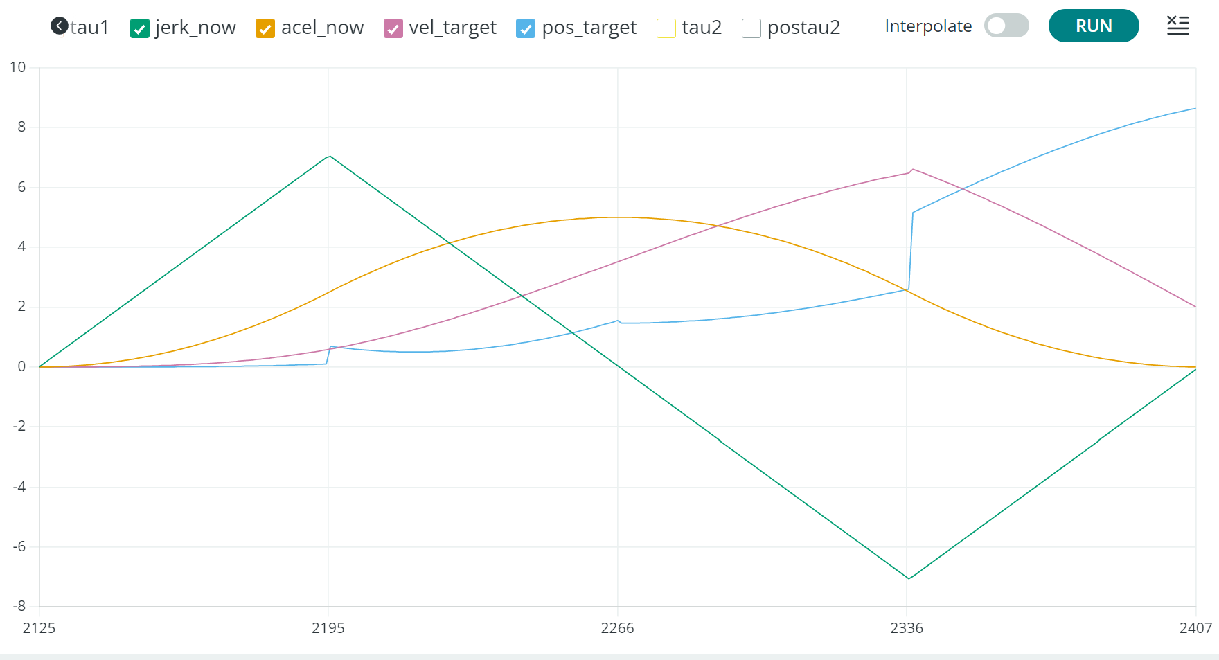
So, we inter the execution loop, with a currentTrajectoryTime, and fall into the time segment, based on above transition time calculation. eg. [t0, t1]
void S4_CurvePlanner::RuntimePlanner(float currentTrajectoryTime) {

     //float currentTrajectoryTime = (millis() - plannerStartingMov

if (t >= t0 && t < t1) {
    // Code for the [t0, t1] time range
    tau1 = t - t0;

    jerk_now = jmax / T1 * tau1;

    acel_now = (jmax / (2.0f * T1)) * pow(tau1, 2);

    vel_target = (jmax / (6.0f * T1)) * pow(tau1, 3) + vs;

    pos_target = (jmax / (24.0f * T1)) * pow(tau1, 4) + (vs * tau1) + qs;
}
1 Like
Nice work !! It wold be interesting to add explanation of your GCode commands in your GitHub repository 
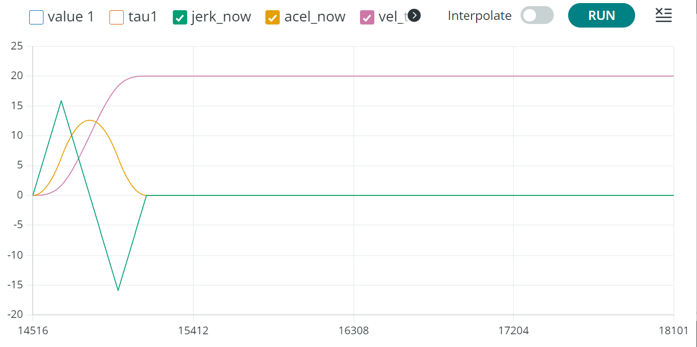
I have the jerk and acceleration curves looking ok. The velocity curve is almost good, while the displacement (position) is a bit weird looking.
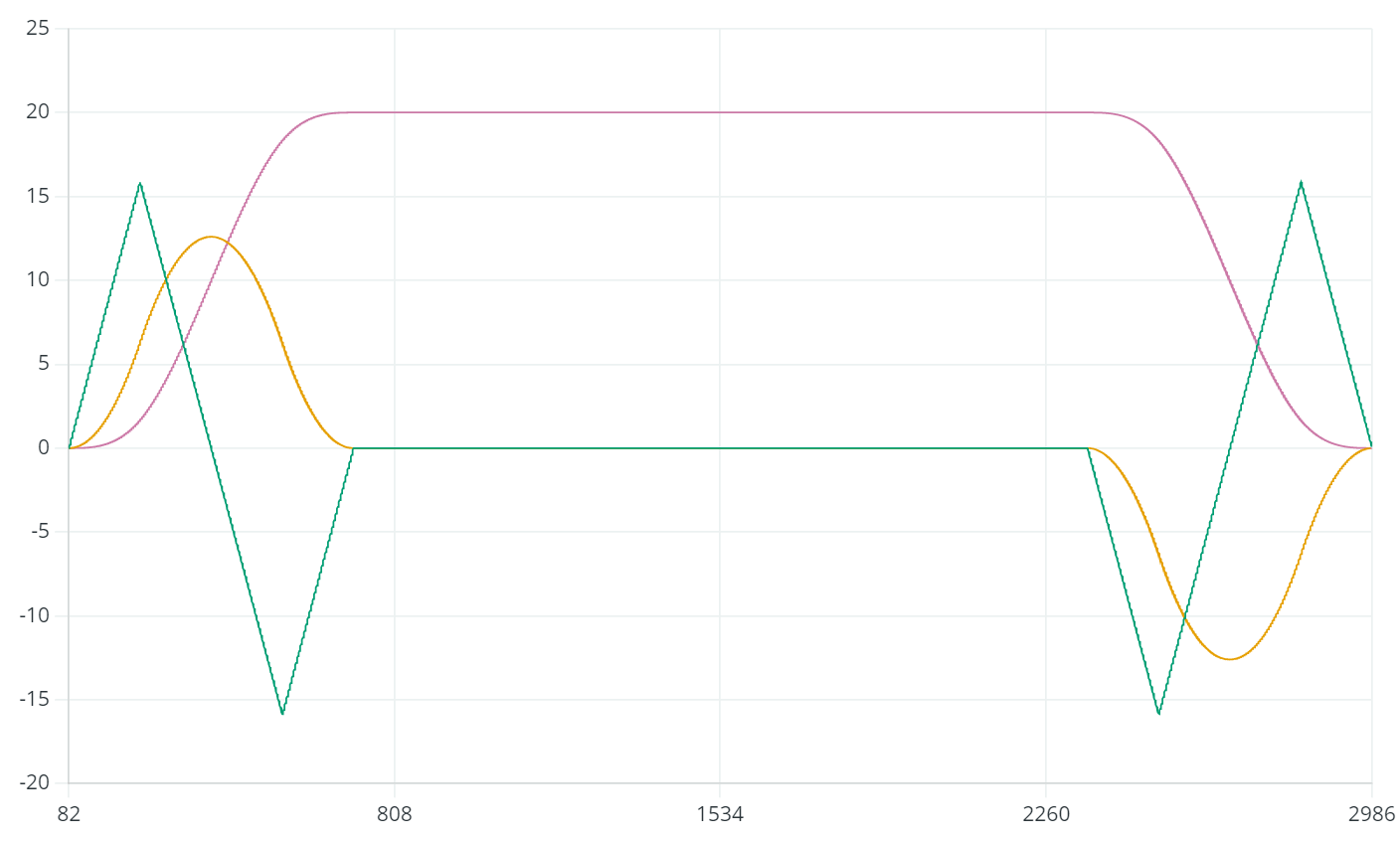
This is just the first half of the move. The other half is symmetrical.
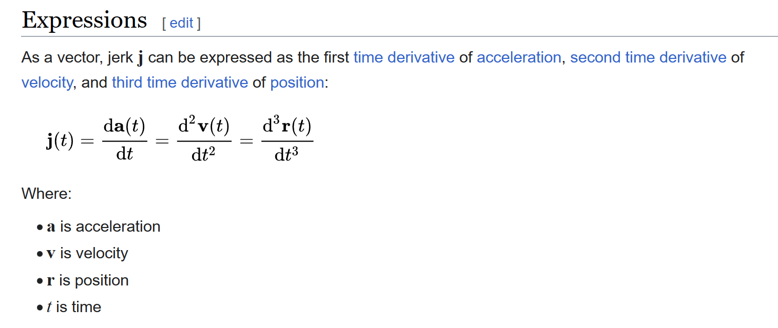
I suppose, if we have the jerk (linear) and the end position, within each time-segment (T1 - T15), we can translate that to position (displacement) ?
The overall concept does look fine, I just think some of the math is wrong. In the paper there is a typo in the formulas.
See the calculation for q4. in the formula there is 2max variable, but it has no reference.
Ok, I have something working now.
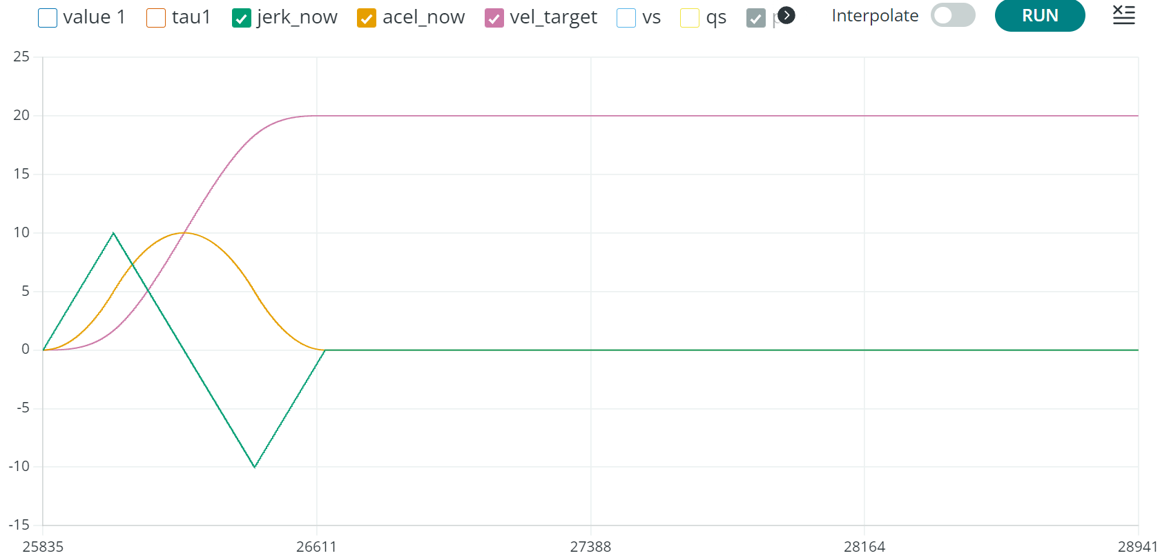
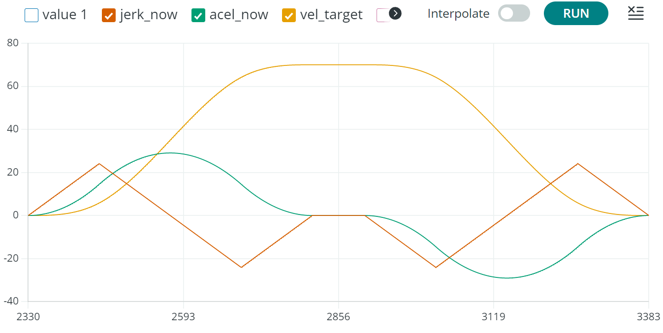
Here are two different moves. One has low snap and jerk, the other has higher snap and jerk. This difference is expressed in the shape of the ramp. Higher/lower acceleration. Maximum velocity is set to 20.
Feel free to find some bugs !
And there is the full symmetrical move. A harmony of mathematical precision 
1 Like
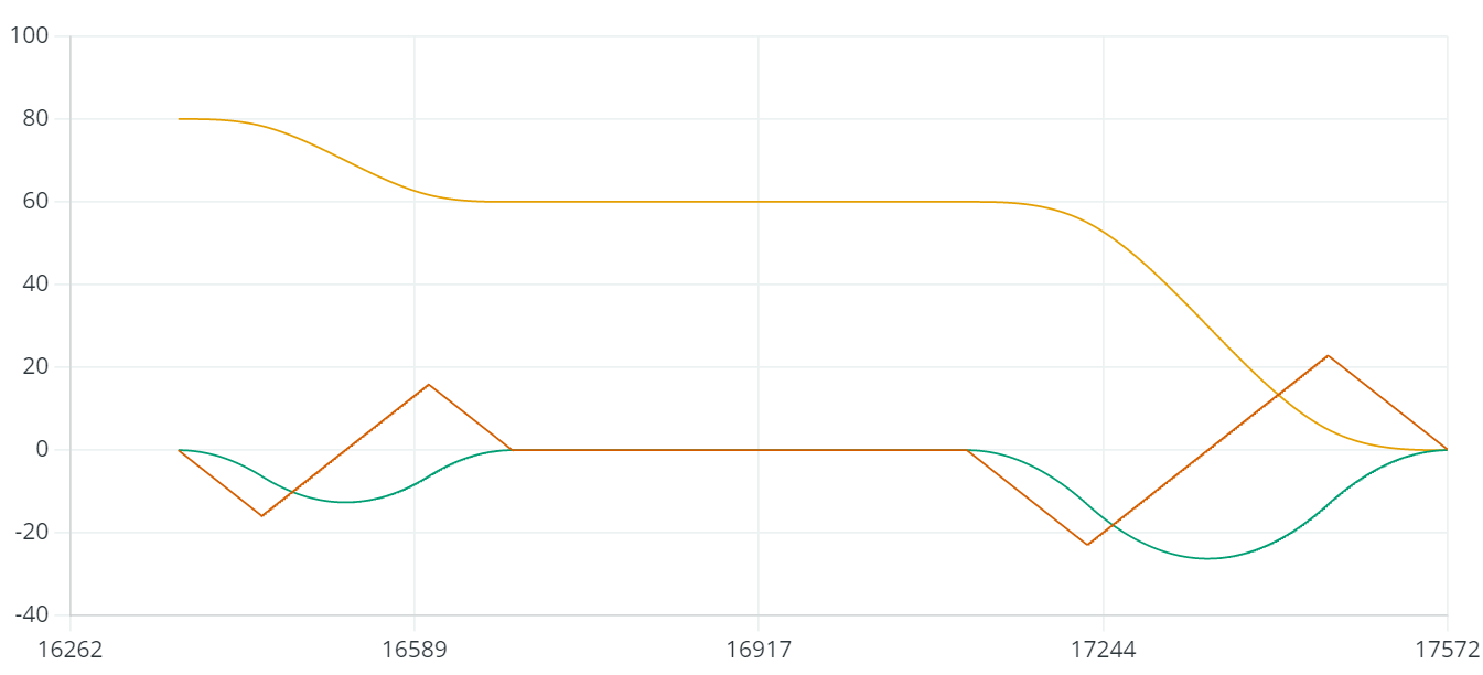
This is a move using all the accelerating and decelerating time-segments, since max-jerk is reached at 20. The jerk restriction is therefore minimizing the change in speed over time and flattens out the acceleration a bit.
Edit: I had a bug in some math. This is how the jerk restricted move should look like. If I have higher jerk limit, then the jerk(tip) above 20, matches the time in constant jerk here:
Edit Edit: Yet another math-bug, I was calculating the cruise time wrong.
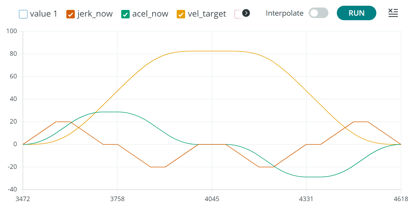
And this is the same move without jerk-restriction.
Ok, now it covers cases where initial velocity is greater then current max velocity and if initial velocity is greater then 0. This is a example of what happens, when there are no more commands in the buffer / last command.
I’m starting to see the potential in timing these moves using timestamps on each command. Usually a Gcode is bundled with X and Y coordinates, I suppose when coordinating multiple axis on various controllers, each move should have a timestamp?
Another potential just came to my attention. Up until now, my focus was only the trajectory planning for each motor-controller, but the paper describing the math-concept does not stop there.
Using the same math, we can create multi-axis synchronized moves. Basically it calculates the trajectory for each joint/axis and with that a unified “scaling factor”.
In theory this could be handled on the host/sender, communicating modified jerk, acceleration, velocity etc. to each sub node, for each move.
In essence it is what Klipper does for steppers more or less.
1 Like
This is great stuff! Can’t understand why there’s so little replies here. Do you have a latest version online? The version on Github seems to miss the calculation of the Tf variable (to determine the total movement time)
It seems to me that feedforward works for things like clean room robots, not skateboard motors or balance boards. But there’s also a big gap in simplefoc in terms of the feedback modeling needed to take advantage of s-curve type motion. Like for one thing, I don’t see shaft inertia being modeled. Sticking a big flywheel on the motor shaft immediately makes pid tuning better if you take out shaft inertia, because it then dominates everything else. Also, the dynamics has to transform the endpoint kinematics to the motor shaft, which could be extremely nontrivial…even a gearbox is nonlinear.