There is several initial settings of the AS5600, that will make it do different things and influence the speed and accuracy of the angle measurement. I should like to find out the default settings, that the FOC software use. How do I see that? Is it normal to change these default settings?
Regarding the nominal field strength from magnet:
According to page 8 in the datasheet, the sensor expect a magnetic field strength in range of 30 to 90 mT from the magnet. I know, that the field do fall off rapidly with distance from center of a simple magnet (look magnetic dipole), and then this range is not that big. I guess that the sensor do work outside this range, but with lesser accuracy.
You can read a status register (page 20) in the sensor about this field strength. Is it part of an initial procedure, to ensure, that the field strength is within correct range? How do the sensor and FOC software react, if the field strength gets outside this range?
If you set the sensor for a fast response of 0.29 ms you should have a one sigma noise level of 0.043 degree of the measured field angle. (se page 8). However I saw one other guy here, that measured a 1 sigma variation of about 1 degree, and it is about 20 times higher. https://community.simplefoc.com/t/magnetic-sensor-measurements/4758
What may be wrong in this case?
This is just a simple calculation regarding a possible external disturbance:
If you have got a long wire with a current flow of 30 Amp, you have a field strength of 0.6 mT in a distance of 10 mm. If you got such a wire in a distance of 10 mm from sensor, it will be able to cause a change in the measured angle of 1.1 degrees, when you have 30 mT field from magnet.
For various reasons, people often have problems with the AS5600, which is why we don’t really recommend it. Other sensors (e.g. AS5048A, AS5047) have better performance and users have less problems working with them with SimpleFOC.
One of the main reasons is the relatively slow I2C interface speed, in conjunction with the very inefficient way the I2C is used in the default Arduino setup. This will limit you to a loop speed of around 1-2kHz, which is fairly low for BLDC control.
This is hard to say, and will depend a lot on how the measurements are made. In the case of SimpleFOC, I think many users face issues with the magnetic sensors related to magnetic noise (esp on unshielded motors) and electrical noise (due to non-optimal cabling and PCB layouts). There is also the question of tuning the control loops and timings, which can be another source of problems.
The default driver included in SimpleFOC reads only the angle returned by the sensor. It has no provisions for dealing with magnetic field strength or the sensors configuration registers. Whatever configuration is set on the sensor is what is used.
We also have a dedicated driver for the AS5600 here: Arduino-FOC-drivers/src/encoders/as5600 at master · simplefoc/Arduino-FOC-drivers · GitHub
It’s under development so YMMV but it should allow you to read the magnitude register and read/write the settings. What you do with this power is however up to your user code SimpleFOC doesn’t deal with the other registers.
Thank you runger. I shall then look into the datasheets of AS5048A and AS5047. The reason I asked about AS5600 is, that it got a tag on the this website.
When I look your link to GitHub, I see some code for these other sensors as well, so I suppose that you will be able to see how these other sensors normally will be initialized.
I shall likely have some questions, when I have studied this.
I have looked on the datasheets and the code. I do not understand it in detail, but I hope my questions will make sense anyway. I think the AS5047 is like the AS5048A that includes the possiblity for ABI hardware signals, and I do not need that for understanding. So I stick with questions regarding the AS5048A, and I have changed the header name for thread. I looked the datasheet here: https://www.mouser.com/datasheet/2/588/AS5048_DS000298_4-00-1100510.pdf
The AS5600 seems to have significantly more internal settings, and therefore also more internal settings, that can be wrong. Perhaps this is the reason for some user problems with it as well. The AS5048A seems more simple.
The specified field from magnet on sensor should be in range 30 to 70 mT according to page 8.
When I look at the driver software, it seems that the readDiagnostics() and readMagnitude() might be used to check this field strength. But I get lost understanding nop(). Furthermore, I do not think the datasheet is that helpful in specifying how you should interpreet the output from these internal registers.
If the field strength is not within this range, I guess that the measured angle is calculated and delivered anyway, but the accuracy may not be within specifications. If the field is significantly below 30 mT, then I guess that the noise level of the angle result should increase.
I see a propagation delay of 100 us for an angle measurement (page 8). I guess, that when you call readRawAngle(), it will not be acceptable for the software to have a busy-wait in 100 us. How is this handled? Do you read a preveious measurement? Do this measurement got a time stamp for instance by calling micros()?
I noticed some way of measuring the rotational speed, that includes some use of micros() to make a time stamp of the angle measurement. Is it the right interpretation, that this is a way to know the time between two angle measurements in order to calculate a speed?
unfortunately no… the datasheets are not at all useful for this. The value returned from the magnitude register seems to be in the range of 16 bits, and values around 5000 or so seem to work well in my experience. But it would be good to know what the actual units are.
I’ve never really paid attention to this number. I am not sure what it really means. The time taken in reading a “fresh” value over the SPI is much lower, for 1MHz SPI it would be around 64us to clock the data, but the SPI speed could be set up to 10MHz.
The sensor will have an internal propagation delay, in the AS5048A it isn’t configurable. The AS5047 has more configuration options, especially the AS5047U.
In addition there will be latency introduced by the data transport when reading the value. With SPI this latency will be much lower than I2C, but with ABZ type interfaces it is even lower still.
So reading a sensor value is never perfectly accurate. There will always be some inaccuracy introduced in the time domain in addition to the measurement inaccuracy of the sensor itself. Its the Heisenberg principle of motor sensing
Yes, it is a general way to take the differential to obtain the (angular) velocity. It works based on the MCUs internal clocks and is independent of the sensor hardware. But it is subject to errors, both in terms of latency and in terms of timestamp errors.
I tried to look for information about this propagation delay of 100 us, but as you, I could not make sense of it. I know, that the voltage from hall sensors are very low, and therefore I would expect, that some time should be needed in order to measure an accurate value, but it is all I can say. Will the SPI protocol allow the sensor a delay to return data? Or must it respond within a specified time? I cannot see support for triggering a measurement, and then later reading the result.
I have tried to do a calculation on using such a sensor for control of a low speed on a motor, but with a sample time of speed of 0,5 ms (2 kHz). It is the same, that can be seen in this video with a 5 rotor pole micro motor used for tacho feedback. The voltage from this tacho generator is amplified and then measured by an Arduino Nano AD converter.
This tacho generator provide an rms ripple of the speed signal of about 5% of the speed. The speed is 30 rpm.
Assume the AS5048A was used for measuring the speed. In 0.5 ms you have got a change in angle of 0.09 degrees. According to data sheet, the rms (one sigma) noise is 0.068 degrees. When you subtract two angles, the noise on the subtracted value should be 0.096 degrees. So in this case the expected noise of signal is about 107 % of speed to be measured.
Am I right in this evaluation, that this small DC-motor is a much better sensor for speed information that this magnetic sensor?
SPI is a synchronous protocol. When you send 16 bits of data, the sensor has to reply with 16 bits of data. the sensor SPI protocols are all designed in different ways, some (like the AS50xx sensors) return the response to the previous read on the next read, so to get a “fresh” angle value you have to read 2 angles. Others exchange 24 bits of data, returning the angle in the lower 16 bits, and other similar schemes. No matter which, with SPI you get the data fast - there is no delay in the protocol where the sensor could “wait” for data.
When reading the data, the sensors all “latch” the current value so your read of the angle register returns a consistent value. The next read of the angle could return the same value, or an updated one, depending on how much time has passed and how the sensor works.
No, I would not say so. I’ve used this sensor a lot, and there will be no issues at 30 rpm whatsoever. At 3000RPM you may run into performance issues, and 30000RPM is probably beyond the sensor’s capability.
But for 30RPM, using this sensor and attaching a magnet will be a much easier and more workable solution than trying to attach the two motors and trying to interpret the BEMF signal of the second motor to recover the position. I think this is particularly true for your application, where stopping and slow movement are important use cases, as the “motor as sensor” will only work above a certain minimum speed, since at low speeds the BEMF signal will be too small to measure reliably.
I can’t 100% follow your calculation. In the end, the position needed is in electrical coordinates, so the accuracy is even lower than you state. Practically, the commutation may be a bit less than optimal, but 0.068° physical angle error is still only 0.748° electrical on an 11PP motor, compared to the 90° electrical that we’re trying to position the stator field ahead of the rotor.
So I would not place too much store in this value from the datasheet. In general the datasheets are very bad at clearly defining these dynamic error conditions. Some of the MPS data sheets are a little better, giving you filter curves and cutoff frequencies for the signal.
I think if you really want to analyse it you can assume the signal follows the “real position” with some error terms modifying it:
a phase shift which is dependent on speed (and could be corrected) due to internal propagation delay and sensor-reading latencies
a filtering component due to the maximum bandwidth of the sensor
a filtering component due to the sensitivity of the sensor and the digital representation of the data
a noise component due to external noise and the sensors measurement accuracy
I’m not an expert on this by any means, but I assume Matlab would let you model this without too much work?
Thank you for explaining the SPI protecol. I then tried to read some more about that in the data sheet, and then started to understand a lot more including the meaning of nop().
I have tried to read a bit more in datasheets for AS5047D and AS5047U. That makes me disagree, to “you have to read 2 angles”. I think, that the measurements are made continuously in the sensor like “free running”, and measurements repetition time is the propagation delay specified time tdelay. It means, that when you read an angle, it will be the last updated value from the sensors own cycle. The sensors do also provide ABI signals or PWM signals on other pins. Therefore the sensor needs to read the magnetic field continuously without relying on some timing from a SPI read command.
I base this on datasheet AS4047U page 11:
“The AS5047U generates continuously the angle information, which can be requested by the different interfaces of the device. The internal 14-bit resolution is available by readout register via the SPI interface.”
And page 13:
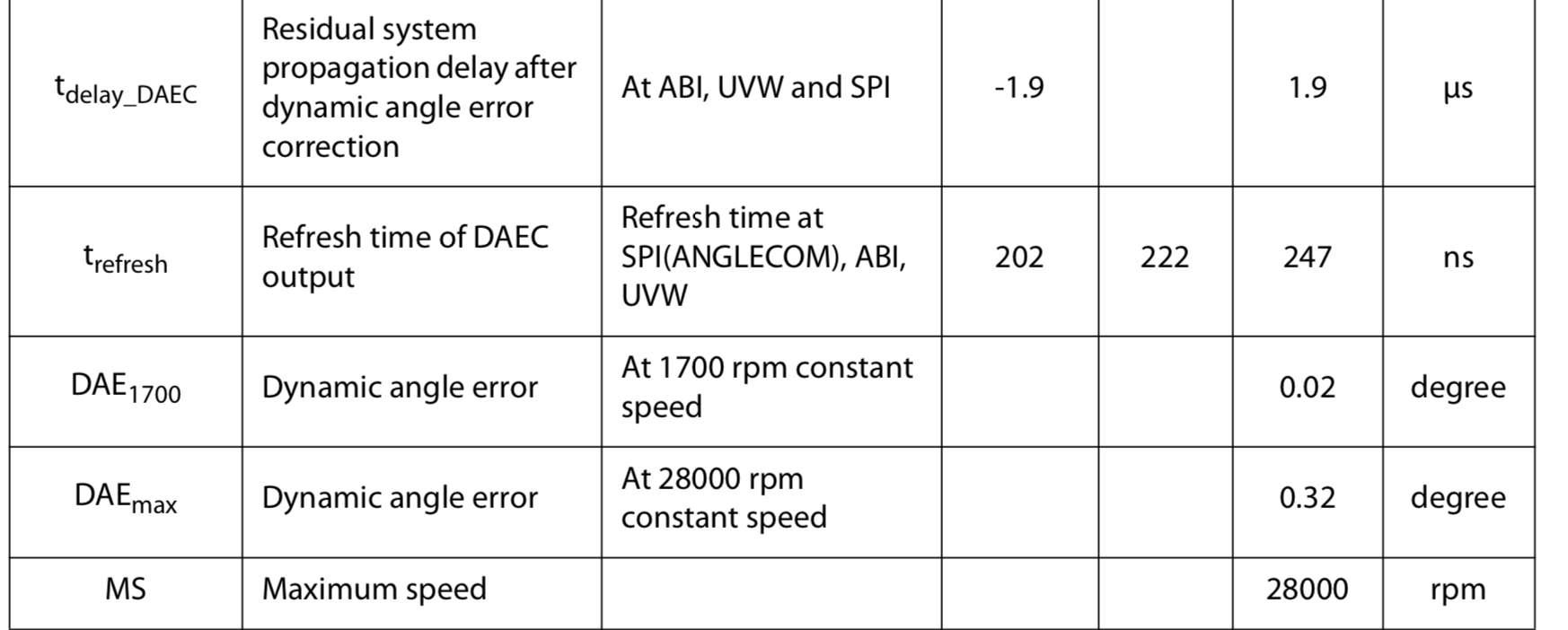
“The propagation of these signals through the analog front-end and digital back-end generates a fixed delay between the time of measurement and the availability of the measured angle at the outputs. This latency generates a dynamic angle error represented by the product of the angular speed (ω) and the system propagation delay (tdelay).”
At page 9 tdelay is specified to be between 90 and 110 us.
The need to read two angles arises from the fact that you can’t know what the previous command was. So in absence of further information you have to assume the previous command was not a read angle and read twice.
It’s also the case when you want to read another register - anyway, hence the nop() as you realize.
If you’re continually reading only angles then it is safe to read just once, I think.
Note the dedicated driver has a mode for this I called it “fastMode”…
I asume, that the shift register to transmit data to the master is loaded with the latest measured data just before data are send to master from this shift register. It would be odd, if the shift register was loaded at the end of the read command. But you cannot be completely sure without testing, because I do not see, that it is specified.
This own measurement cycle behavior of the sensor cause me to think of some problems, that might arise regarding calculation of speed, because I see no simple way to synchronize to the measurement cycle of the sensor.
For the case in video, no position information is needed, because the main motor is a brushed DC motor. For FOC you need position information to place the angle of the current vector, and therefore a small DC motor as tacho generator is not applicable for that. But it might be relevant, if you need accurate speed information as well as a high update rate.
I have not tried these magnetic sensors for this, and I guess, that you have not tried to use these brushed DC motors in order to measure speed. So we are both on somewhat theoretical ground here regarding the other solution. I read what you write, that you have not seen problems at low speeds even though the calculated noise on speed seems significantly higher from an magnetic angle sensor.
At 30 rpm the BEMF voltage from this micromotor is about 1.1 mV. It is an easy level to measure accurately, and I have not seen problems in doing that (I think 10 uV would start to cause challenges). For higher speeds I shift to another input with 10 times less amplification on the BEMF. This micromotor can also work at speeds up to 75.000 rpm, which is the max specified speed of the motor. However, I am concerned about wear of brushes and long term durability.
You need a high gain in the control loop in order to get a fast load step response and a stable low speed, that can withstand motor cogging torque. My experience is that the noise from the ripple (noise) from the BEMF (about 5 % rms in the speed signal) do limit how high I can adjust the gain. It is however at a higher speed at about 800-1500 rpm of the motor, that this ripple noise starts to be a challenge and causes a higher noise current to the DC motor and some audio noise from the motor as well. This ripple noise is proportional to the speed until I start to limit the bandwidth of speed signal with an RC-filter at 160 Hz. At 1500 rpm the ripple frequency is 250 Hz.
Assume, that you have got a magnetic sensor with a 90 us update time period. When you read the angle register every 500 us, then sometimes the measured angle was updated 5 times with a 450 us time difference and sometimes updated 6 times with a 540 us time difference. At a speed of 1500 rpm, it means that the changed angles in the two cases are 4.05 degrees and 4.86 degrees. You have to assume a time of 500 us between the two received angles. Therefore the calculated speed vary significantly and as a rms-value of noise about 0.57 degrees of a 4.5 degrees signal and it is about 13 % of the signal. The noise on the measured angle is 0.085 degrees, so it is much less in this case at 1500 rpm.
Therefore this calculated noise in speed signal from this kind of sensor will be higher compared to the DC motor, and it will cause that you would need to reduce the loop gain and performance. I am not sure about how much the higher noise will be a problem at 30 rpm, but as you say this have been tried and have been successful.
There might be a way to synchronize to the time cycle of the sensor. In some intelligent way you may be able to track the cycle time of the sensor and calculate a more accurate speed value. Then you know when five or six angle measurements had occurred when angle was read. The AS5047U is more advanced, and have got the possibility to read a speed value, and I think this value will have less noise because it uses the sensors own clock.
Many factors are in play here, so without actually trying it, it is hard to be sure.
I tried to look for the price level of some small PCB with these sensors. The price level of the AS5600 is only 1 euro while AS5048A is about 6 euro and AS5047U is about 8 euro.
Reading 1mV should indeed be possible with some amplification, but the question is of course how much noise you have on this signal.
Still, I am sure that (with a lot more work!) you can turn the small motor into a sensor that works above a certain minimum speed.
In terms of the magnetic sensors, the SPI interface is definitely fast enough for lower RPM values. But if you want to go fast, then you should be looking at the ABI modes of the sensors, which eliminate the latency problem more or less completely.
And if you’re more interested in building your own sensor processing chain (which will be a lot of work) based on offset sine outputs from some sensor (which is what the motor would be, in the end) then there are solutions for inductive resolvers you could look at which might be a bit easier to work with…
Either way, let us know the results when you decide and implement something.
You mean the extra work is the electronics with the op-amp - right?
The ABI modes of the sensors do also depend of the measurement cycle of the sensor each about 100 us. Therefore, you can not expect to have the AB signals updated outside the measurement update each 100 us. With the SPI it will depend on how often and when you read the sensor. With a 1 MHz SPI clock, you should be able to get the angle 16 us later. But 100 us+ is still rather fast. At 20.000 rpm it will however cause an angle of 12 degrees and an electrical angle of some times more with more poles.
Regarding the noise in velocity at very low speeds in range 1-3 rpm, I noticed an interesting video from Skyentific with a comparison of three motor controllers, that do perform differently with same motor:
It is known, that cogging torque can cause such variations (both for brushed and brushless DC-motors). Some did made compensations by some calibration with a recording of the motors behavior. But I think the quality of the encoder, and how you use it, is in play here as well. I did also find other videos on youtube, with similar small variations in speed, including a 4 year old video with a SimpleFOC program, with the parameters NOT optimized: https://youtu.be/Y5kLeqTc6Zk&t=244
However you need to look carefully with a constant low speed setting to see this noise in speed. The motor audio noise is also interesting. I also tried to make a similar video with my setup. Compared to the controllers by Skyentific, I think it can be placed as average performance. https://youtu.be/Sp55jztsI80
I should love to see a similar video of a motor with SimpleFOC, a known encoder, and optimized parameters.
But with ABI and hardware support on the MCU side I think you could do it…
At least the AS5047U Datasheet thinks so, I can’t claim I’ve actually done it
The MA734 from Monolithic advertises 3us constant speed propagation delay with an update frequency of 980kHz, and operation up to 60kRPM. Again, I haven’t tested it, and again you’d certainly have to interface using ABZ, or even UVW type interfaces to reach such speeds.
That’s just two examples, there are further magnetic sensors designed to operate at high speed.
I think it looks like quite nice performance, actually, especially for a dc motor.
For the magnetic sensors, also the quality of the magnet, and how you mount it. This is where many systems have issues.
And then there is electrical and magnetic interference, power supply issues, and all the other system components that play a role…
So there are really many factors, all of which can have an impact…
Using the micro motor seems to be working very well as a tachometer but of course you don’t need position to control the DC motor.
The magnetic sensors give absolute positions right after boot-up, which makes them very practical and easy to use for many applications.
I think the datasheets again is a bit hard to interpret. The sensor have got a prediction function that may be able to advance the signaling. I think, that the basic cycle for reading the magnetic field sensors is the same. You also got sensors, that output the sine and cosine values directly as analog signals, and I guess the AD-converters in the microcontroller might be faster, than in the sensor.
There is sensor less algorithms, that can estimate the rotor electrical angle. I know a bit about the dynamics of synchronous generators used on power plants and diesel generators. By measuring the real and reactive three phase power, you should be able to predict rotor position relative to the applied voltage phase. I would think that such calculations would be inaccurate at low speeds, but at high speeds I think this way should be reasonable accurate. But you likely would need some good calculation capacity.
At zero speed, it is like you got a torsional spring that aim back to “zero” position. It is due to a proportional factor on the position error to the aimed motor current, and an integration part of the speed controller to the aimed motor current. I got the same feeling with my DC-motor setup, but it do not have position control, so it is the integration part of the speed controller, that do it. A higher gain here cause a stiffer torsional spring, so the motor react harder with torque on angle changes. In order to reduce velocity changes due to cogging moments and ordinary load changes, this spring needs to be quite stiff. At least in my set-up, this stiffness seem much harder than seen in the video.
I have noticed, that AMS Osram also produce a magnetic hall angle sensor named AS5116 with analog cos/sin outputs. https://ams-osram.com/products/sensor-solutions/position-sensors/ams-as5116-position-sensor-sincos-output
The datasheet is from 2021, so it might be a bit newer component to be produced. In this way it will be the ADCs of the MPU, that measures the hall signals. The components are still relative expensive, and I think it is because of lower production numbers. Perhaps other manufacturers produce similar sensors.
But this way should eliminate errors due to not knowing the exact timing of the measured field values. When you have the MPU measure directly, you will know exactly when the field was measured. It should also eliminate possible timing problems at higher RPM values. But the possible noise in the signal still remains.

")