I have a linear motor I’m attempting to drive with the FOC library - the forcer, the part that moves, and contains the electromagnets for generating movement, is 2.7 inches in length. While the track of permanent magnets, which stays stationary is 8.6 inches in length. I’m using a custom high resolution encoder with this design, and due to the GenericSensor class requiring a distance in radians, my question is: What would 2pi radians be in this case? 2.7 inches as that’s the equivalent part of a traditional motor that would spin if it weren’t linear? Or 8.6 inches, because if the linear motor was “rolled up” its circumference would be 8.6 inches?
Hi @zbaltzer , welcome to SimpleFOC!!
Nice question!
The 2PI radians corresponds to one complete turn of the motor.
So I think your intuition of “rolling up” your linear motor is the correct one.
Another question is the number of pole-pairs of the linear motor. I think maybe you are free to choose it, but it has to match the 2PI scaling you define in your sensor.
So as you run the commutation through one electrical revolution, the linear motor will move a certain distance, call it D. That would correspond to a setting of 1PP on the motor, if you make the sensor return 2PI for this distance D. Or you could make the sensor return 2PI for n x D (n is any positive integer), corresponding to a motor of n pole pairs.
Does that make sense? (Note: never used a linear motor myself with SimpleFOC)
Hi runger, can you please elaborate a little more, I don’t think I fully understand your conversion? I am also trying to get a liner motor running with SimpleFOC library and not having a lot of luck even to get some basic operation. I am running a bluepill with V2.0.4 shield and standard AB line encoder. In open loop position example I can get the mover to shift around ±2mm quite smoothly with target angle but it won’t do anything more than this no matter what I try. I’ve tried lots of different pole pair numbers in the BLDCMotor instance but it doesn’t seem to change anything. Any help would be appreciated.
If you carefully write a description of your system we might be able to help more, but that’s not an insignificant amount of work either.
I think you are assuming too much about how complete SimpleFOC is. It only drives the motor. The pitch of your leadscrews or ball screw will determine how much linear motion per rotation you get. I am guessing this is an art project or something.
If you use open loop angle mode just tell it to do like 10 pi radians and see what happens. It should rotate clockwise or counterclockwise like 5 times. If it goes counterclockwise, you should reverse any two of the motor wires so it goes the right way to simplify things…
Once you got that working, get the encoder working and switch to closed loop mode, and you have a very nice customizable servo motor solution that is brushless.
Hi @Zerpoint , welcome to SimpleFOC!
Well, TBH I have never run a linear motor myself, so I’m talking kind of theoretically.
My point was that in a linear motor the mover (equivalent to the rotor in a regular motor, with the permanent magnets) moves a certain distance, linearly, for one cycle through the sinusoidal commutation pattern.
Setting a certain phase voltage (-90deg electrical?) should snap it to a certain position, and then running the motor through one electrical revolution should move it a certain distance.
This distance corresponds to “1PP of movement” or one electrical revolution of commutation…
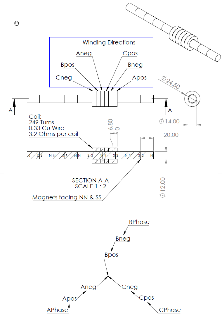
Perhaps if you could share some diagrams for your motor showing the magnets and the windings we could give more concrete advice…
Wow, that is interesting.
Where does the encoder go? Are you using the type with a reflective tape with pits and an optical sensor?
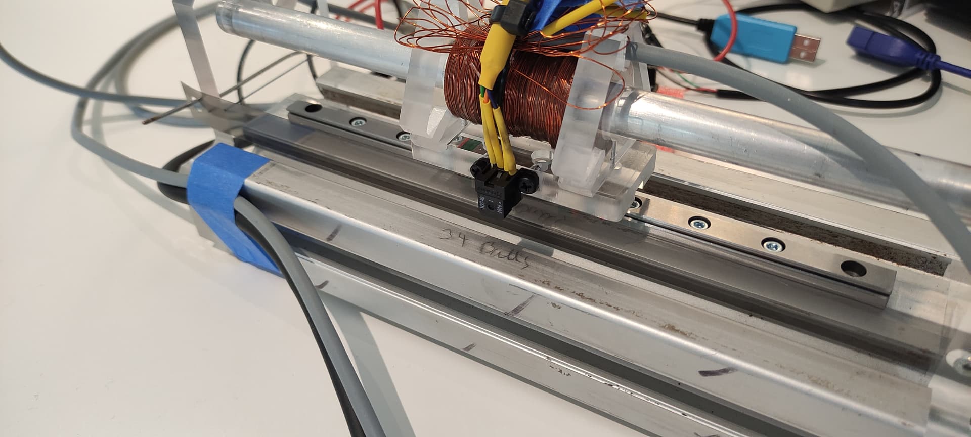
Hey, this looks like a really cool setup.
What resistance are these windings? I would suggest running an open loop test first:
Perhaps using the open loop position mode, with the motor set to 1PP, or even just running a loop through one electrical revolution manually, like our alignment or sensor calibration code does.
Basically, set a known angle (-90deg) to the phases, and then advance through one electrical revolution (2PI radians in position mode with 1PP) while calling sensor.update() to update the sensor position.
If you move back and forth in this way, you can check the sensor readings are reliable, and can tune the sensor conversion factor.
For the sensor, you’ll have 2 conversions - one that takes ticks into radians for running the BLDCMotor, and another for your higher level code that takes radians back into a linear distance.
Oh haha it’s an actual linear motor. Very cool stuff. I’ve often wondered if you could use the sensor from an optical mouse, too. Combined with periodically resetting the system using limit switches etc. it could work.
Depends how much accuracy you need and so forth.
P.s. when you connect the scope, don’t measure the voltage, measure the voltage across a sense resistor or something. I also found that common ground issues with cheap scopes prevented me from measuring the current across more than one sense resistor at once, given the way the inverter works. A good scope would have separate ground for each probe and that should work fine with sense resistors.
@runger Each phase is around 12.2 ohms…
Okay I’ve had some progress! Turns out the knockoff bluepill isn’t happy using any PWM pin as an output, so using the standalone driver utility (which is super helpful) this tracked down the main issue. Open loop ran fine, and I’m now playing with position control trying to get that running!
@Anthony_Douglas Thanks for the tip on the resistors, given I’m up and running I’ll see how far I get without this measurement and keep this in mind.