Which boards are you referring to?
Cheers,
Valentine
Which boards are you referring to?
Cheers,
Valentine
B-G431B-ESC1, from the original post
The board suffers from very poor thermal management. It’s only designed for quad-copters with strong forced air cooling. Unless you use liquid cooling for other use cases, it fails very quickly.
Cheers,
Valentine
It is very nice to see how my simpe question above stirred such highly interesting conversation here and in the new thread on regenerative breaking. I learned a lot by the answers and the links to papers. Since I started this thread, I wanted to update you on my findings on the probably death cause for those boards. After finally hooking up the scope, I am now pretty sure that the real reason was not the BEMF, but more the weak, cheap power supply I wanted to use, which seems to be simply too weak, shuts down when high current is pulled and restores power very quickly after that again (so quick that the CPU does not reboot in most cases). My suspicion now is that this leaves the whole circuit in a somewhat undefined state. As soon as I use my Lab PS, it works fine.
Regarding the temperature, I had no problems so far with the boards, but I don’t pull more that 9A per phase @ 24V and use small heatsinks on the MOSFETS and a tiny fan. I also monitor the temperatur using the onboard sensor and normally it doesn’t get hotter than 35 degrees C or so.
Would it get better if you solder very large bulk capacitance close to the board?
I could well imagine, but honestly, I don’t want to rinsk any more boards. My plan is to go for a larger PSU and add capacitance to the individual boards (which is a bit of a space issue, but solvable). Since my hardware experience stopped in the early 90ies, do you have any suggestion as to which values I should use or is there anything else I should observe? I thought of something like 470uF/35V @Vbattery=24V. The new PSU I chose is however not yet available, so this needs to wait. Right now I am waiting for new CAN bus transceivers, since the ones I had were fake and died, so no real progress any time soon anyway. No real fun with components these days…
So, since I started this thread, here is some update on the current status. The good news first is that I did not break any boards since this discussion started ![]() , but of course, I faced problems from all directions. One of the biggest issues was a loose magnet, which turned out to have a very strange effect ( we discussed that in a different thread). I only noticed this, becaue I modified my B-G431B-ESC boards to support a full SPI and now I can monitor the diagnostic outputs of the sensor and when the magnetic field deviates too much from the expectations, then I stop the motors. In addition, I now have sensor calibration and use the same routines but much coarser for a quick sensor test at startup. These steps eliminated one source for errors that might have killed my ESC boards in the past. On the BEMF side I reduced the supply voltage to 12V and added code to closely monitor the voltage on each board. The results were surprising in that the generated EMF is much higher than I expected. I measured up to 16V for a 12V PSU and that was not even close to an extreme operation of my device. Adding 470uF per ESC did not change much, that’s simply to little in this case. I will go for 4700uF, but need to order capacitors first. Also, I implemented a circuit similar to @Valentine 's, which solved the overvoltage issue, but now I have a problem with undervoltage instead, as soon as the protection circuit kicks in
, but of course, I faced problems from all directions. One of the biggest issues was a loose magnet, which turned out to have a very strange effect ( we discussed that in a different thread). I only noticed this, becaue I modified my B-G431B-ESC boards to support a full SPI and now I can monitor the diagnostic outputs of the sensor and when the magnetic field deviates too much from the expectations, then I stop the motors. In addition, I now have sensor calibration and use the same routines but much coarser for a quick sensor test at startup. These steps eliminated one source for errors that might have killed my ESC boards in the past. On the BEMF side I reduced the supply voltage to 12V and added code to closely monitor the voltage on each board. The results were surprising in that the generated EMF is much higher than I expected. I measured up to 16V for a 12V PSU and that was not even close to an extreme operation of my device. Adding 470uF per ESC did not change much, that’s simply to little in this case. I will go for 4700uF, but need to order capacitors first. Also, I implemented a circuit similar to @Valentine 's, which solved the overvoltage issue, but now I have a problem with undervoltage instead, as soon as the protection circuit kicks in ![]() . Hopefully the higher bulk capacitance will solve that. I will also go for a higher supply voltage again, as soon as I manage to get my hands on a 20V/5W zener diode, but these are hard to get in small quantities and at reasonable prices these days. Apart from that I fought with my CAN bus, redesigned the mechanics of my paragliding simulator, use torque instead of position mode to control the break lines and all this together makes me very happy since operation is very smooth now and feels quite real - as long as I switch off the over/under voltage protection (which I only do under very controlled conditions and at 12V now, I learned some lessons…).
. Hopefully the higher bulk capacitance will solve that. I will also go for a higher supply voltage again, as soon as I manage to get my hands on a 20V/5W zener diode, but these are hard to get in small quantities and at reasonable prices these days. Apart from that I fought with my CAN bus, redesigned the mechanics of my paragliding simulator, use torque instead of position mode to control the break lines and all this together makes me very happy since operation is very smooth now and feels quite real - as long as I switch off the over/under voltage protection (which I only do under very controlled conditions and at 12V now, I learned some lessons…).
As an advice for other users of the B-G431B-ESC1: Be very carefull with your power supply, take generated EMF into account, do not, really never ever, exceed the max specified supply voltage, not even by a little and not even for a very short time! Use the boards option to monitor VBus and if you have the chance implement sensor diagnostics, then do so! The B-G431B-ESC1 is really good, but requires some love, good soldering skills and the on-board aux power supply is very, very sensitive to overvoltage.
Happy holidays
Chris
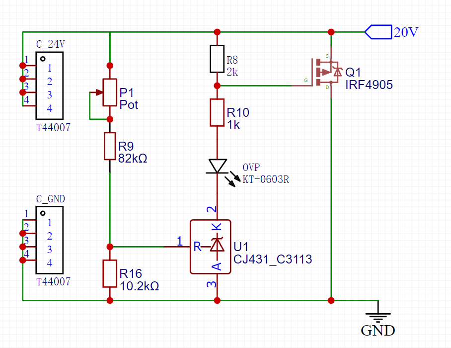
Meanwhile I experimented with a different method which should be more efficient and less space consuming obn the PCB. It is a shunt regulator based on a TL431. The schematic is below.
I have designed it for 24V, but for testing it is all set to 23V and the power supply is limited to app. 60mA. Still I killed already 3 MOSFETS. The first two I can explain (exceeded Vgs max), but the last case not at all. I can see that the TL431 switches properly, the LED reacts and the MOSFET seems to switch as well, but after a few seconds the MOSFET died silently (at 60mA, 23.4V…) and is permanently shorted. Since I am not good at all in analog design, what do I miss here, any ideas? The simulation looked ok. My setup is an awfull perfboard, of course, I cannot exclude anything stupid there, but I checked it a hundred times. One last resort idea I had is that the TL431 might oscilate, but can that really cause dammage to the MOSFET?