Here is a good writeup about the previous proposed line voltage clipper.
It would be cool to see your simulator!
I actually suspect the issue to be old fashioned voltage spikes burning those FETs. Not so much BEMF. If like you say, it simulates turbulence, then it may power the coils and cut power to vibrate the simulator while the other motor exert force. In that case the real question is, is it possible to catch the spike with a brake-resistor or will those fat TVS diodes be up to task ?
Do you know for sure that the bus voltage rises? Or will the caps even out the spike?
You should be able to solder in those large TVS diodes, if you can find some that will clamp the voltage to below your FETs and drivers rating…
If of course it vibrates a lot it could act as a boost converter with many consecutive spikes raising the cap voltage, in which case you also need the brake-resistor or run it on salvaged car batteries.
Full motor control is a huge topic: overvoltage, simple braking, regenerative braking and plugging are special topics requiring their own schematics which massively overcomplicate the design and require separate driver logic/programming. It would be nice if these are included in SimpleFOC however the schematics and PCB driver design may be prohibitive. Could be done however, especially plugging, that doesn’t require a separate circuit. Regenerative braking and overvoltage do.
Perhaps the simplest way of fixing the overvoltage is a TVS with a low ohm bulk resistor in series and both in parallel with the power supply. It’s a bad advise, stupid but relatively simple solution. Your TVS must be able to handle high current and sized appropriately. Zenner may also work. Perhaps.
It’s really hard to solve the issue if we don’t know how exactly the turbulence of this simulator is done, in software. Maybe there is a better way to achieve the same end goal without large TVS diodes. I’m no expert
So, the best thing for me is probably to measure it with the T-motors motor and then take it from there. That’s more a logistic problem than anything else, but easy solvable. My best guess is it won’t be a real problem with that motor.
Anyway, for the sake of learning, I am interested in the answer to my initial question if I can simply have a lead gel/acid battery without any additional circuitry in parallel to the PSU in order to eat up the excess energy?
The question is how do you redirect the power to the battery when you exceed the voltage and it starts running backwards? You need an extra circuit. The way it works, your battery is disconnected, you monitor the voltage and when you switch to a regenerative braking mode you disconnect the PSU and connect/redirect to a step-down buck converter with a charging monitor circuit that charges the battery.
You cannot just keep the battery and PSU connected in parallel. Please don’t do that, you will cook off the battery and it will bubble, overheat and may explode if you inject enough voltage and current.
Really? I thought a battery would naturally stop charging once it equalizes to the power supply voltage. And as I understand it, the motor regenerating will only be a momentary thing, so the battery will eat a little bit of energy but then discharge back down to the PSU voltage shortly after.
To begin with, even a standalone battery in parallel with a power supply without any circuit to protect either of them from each other is a questionable design choice. And when you add the motor, things will go badly. I’d recommend against such a design decision.
As long as the Battery and PSU are at exactly the same voltage things would be ok. But it would be quite an “unbalanced” system - the moment the PSU voltage is higher than the battery voltage, the PSU would start to charge the battery.
The moment the battery voltage is higher than the PSU, it would start to discharge, and the PSU would see the higher battery voltage and probably be destroyed (e.g. when you switch the PSU off).
And during regeneration, both the battery and the PSU would see the higher motor voltage. So the battery would get charged, but probably the PSU would also be destroyed.
→ I guess it needs a diode or active switching element to redirect the currents to the right place…
or to design everything with the appropriate head-room to handle the regeneration voltage, but as Valentine already said, that still leaves the problem of when the motor is turned while the controller is unpowered…
You are making me work on a Sunday. This is the bad idea I was talking about. It will shunt and absorb as heat any voltage between about 13 and 200V, and shunt up to 50A through the power resistors.
The board is 10cm X 10cm. You can use it as a starting point to build your own active shunt. Please do not attach a battery in parallel, it’s a bad idea.
This board below is hypothetically working, in my mind only, 12V shunt. You need to manufacture and test.
No need to do anything in a hurry. That’s the great thing about forums versus real-time communication… whether you write your response immediately or a week from now, it remains well organized.
That board does look like exactly what I was originally trying to come up with. Great use of a zener diode for the voltage sensor. Does it need one more resistor between the diode and transistor gate, or does the diode limit the current enough by itself?
This is an NPN power transistor in a voltage following configuration (not a mosfet), and is controlled by current. The answer is no. The current is already controlled by the resistor. The diode I selected breaks down at 15V and has excellent resistance at 11.5V, with current of about 300mA and pulse current of 6A. This should easily exceed any current a power transistor would need to follow. So you are kind of protected between 12 up to 15V, then it shunts at 15V but then the transistor will drop to a little under 15V (not sure how much you need to read the specs). The transistor itself is good up to 400V but the zener will bomb at 200V, so if you need higher voltage you need to pick a different diode. Also be careful with the zener resistor, it needs to dissipate a lot of power the higher the voltage, may be you can put a few resistors in parallel to dissipate the power better. Also if you expect a really high voltage surge, I suggest you add a high power TVS or a MOV, may be also limited by a low ohm resistor. The high voltage surge will be picked by the TVS and then if the TVS is still alive and the surge front is dissipated the rest will be taken care of the zener. Also, adding a ferrite core outside wil help the TVS/MOV. As you can see there is no limit how deep you want to go into the proverbial rabbit hole.
I’m sure the circuit needs to be tested, as I said, this is hypothetical. The zener resistor needs to be carefully calculated and match the zener and transistor. The zener current also needs to be calculated and appropriate zener selected. You can also add a second transistor to form a darlignton pair, or even a triplet, which will work better. Obviously the lower transistors don’t need to be high power and will be much smaller, but then you need to worry about the extra resistors and diodes to discharge the capacitance.
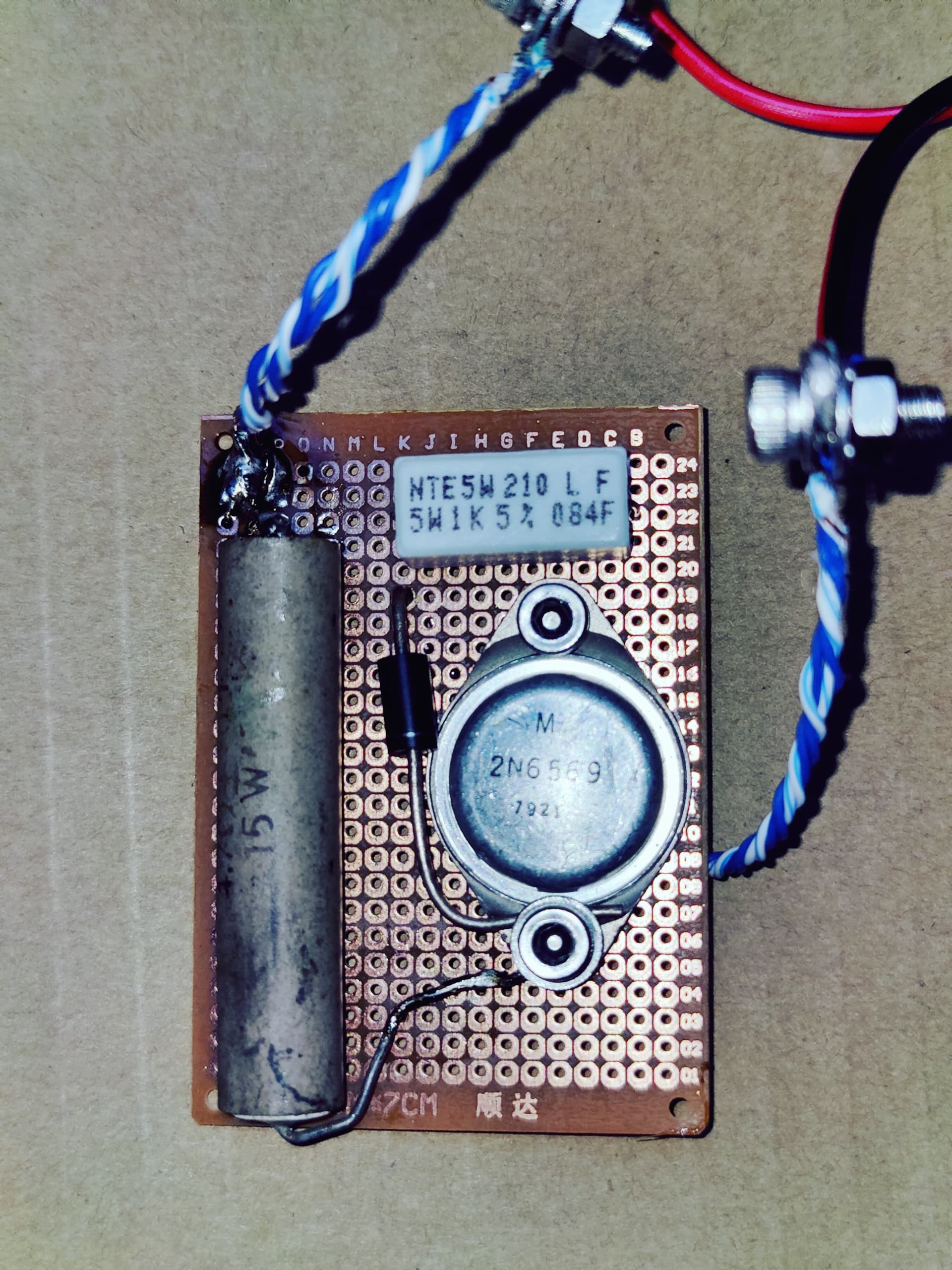
I had some time and soldered a very crude 80s version of the idea and tested it. I’ve been watching Stranger Things lately so I’ll call it “The Thing”. It kind of works, it does shunt quite a lot of current, but the transistor overheats a lot, so active cooling may be required. Also this is a small transistor (10A/40V), and I found only a 5ohm 15W resistor, so the real big one is 50A/1ohm and will be a lot bigger to shunt 50A. Bigger like, huge, 10cm big.
Depending on the application it’s possible to use the motor as a break resistor. The idea is you monitor the bus voltage and if it goes above a threshold you command a non-zero current to the d-axis to dump the energy. Please refer to section 4.4.3 of my friend’s awesome thesis for more information.
Needless to say, this does not protect against BEMF generated when the system is not powered.
I was having my lunch and thinking. You can add a small ultracapacitor, and a low-power MCU and a low-power circuit, then when someone turns the motor by hand it will use the generated power to boot the MCU, start the protection algorithm and charge the capacitor then keep running the protection for as long as there is charge left in the capacitor!
I read, very long time ago, a Sci-Fi short story, some alien planet had this advanced civilization with incredible economy and seemingly endless supply of energy with no visible means of making their own energy, then everyone from the Universe was coming on space-ships to find out how they do it and no one could. Eventually one guy figured it out, they were harvesting the energy of the landing space-ships and storing it and powering their planet.
Cheers,
Valentine
PS Assuming you can recover 100% of a large space-ship’s energy, the energy from an Artemis rocket is enough to power a small town of 50,000 houses, or about 100,000 people for one year. If your planet is 1 billion people, that would mean you will need about 30 spaceships landing every day. Pretty normal, not really out of the ordinary, to have 30 spaceports across the entire planet and have one spaceship per spaceport landing once a day. Of course you will need extra allowance for industrial activities, etcetera, however it is still very realistic.
I was also thinking yesterday that an ultra-capacitor could be used as a buffer to protect a higher ohm but lower amp shunt resistor… current spikes could first charge the ultra-capacitor and then discharge more slowly through the shunt. Not sure its actually possible or practical, but if it is, it might be a way to make the circuit smaller.
This is used in electric cars to quickly charge and discharge when braking and accelerating. Also this puts less stress on the battery and prolongs the life because there is no chemical reaction involved.
I was just thinking… maybe the reason these boards die so easily is due to lack of bulk capacitance. They only have 14 1206 capacitors on board, which I would guess are 10uF 50V. The manual doesn’t say anything about adding any more, and all the photos I’ve seen of them in use didn’t have any electrolytics added, but 140uF seems awfully skimpy to me.
It’s possible the onboard capacitors are 25V 47uF in which case the total would be 658uF, but it’s rated for 6S lipo which is 25.2V fully charged, and those capacitors cost about 20 cents each so that would be a significant portion of the total board price.