Yes, you could also change a bunch of protected registers before locking it again, or leave it unlocked, but ultimately you have to lock it to enable the driver outputs. As long as it is unlocked the gate driver outputs are forced low.
Ok, this aint pretty. But it does work. Buck is now outputting 10v
  Serial.println("Setup driver to 10v!");
  myWire2.begin();
  Wire.setClock(1000000UL);


  Serial.println("Inside Setup!");

  myWire2.beginTransmission(I2C_Internal_Adr); // Begin transmission to the Sensor
  //Ask the particular registers for data
  myWire2.write(0x0B);
  myWire2.write(0xF0);
  myWire2.endTransmission();
  myWire2.requestFrom(I2C_Internal_Adr,1); // Request the transmitted two bytes from the two registers

  while(myWire2.available())    // slave may send less than requested
  {
    uint8_t a = myWire2.read(); // receive a byte as character
    Serial.println(a, HEX);         // print the character
    Serial.println(a, DEC);
    Serial.println(a, BIN);

  }

  myWire2.beginTransmission(I2C_Internal_Adr);
  myWire2.write(0x01);
  myWire2.write(0x01);
  myWire2.endTransmission();
  myWire2.requestFrom(I2C_Internal_Adr,1); // Request the transmitted two bytes from the two registers

  while(myWire2.available())    // slave may send less than requested
  {
    uint8_t b = myWire2.read(); // receive a byte as character
    Serial.println(b, HEX);         // print the character
    Serial.println(b, DEC);
    Serial.println(b, BIN);

  }

  myWire2.beginTransmission(I2C_Internal_Adr);
  myWire2.write(0x0B);
  myWire2.write(0x00);
  myWire2.endTransmission();

  myWire2.requestFrom(I2C_Internal_Adr,1); // Request the transmitted two bytes from the two registers

  while(myWire2.available())    // slave may send less than requested
  {
    uint8_t c = myWire2.read(); // receive a byte as character
    Serial.println(c, HEX);         // print the character
    Serial.println(c, DEC);
    Serial.println(c, BIN);

  }

  delay(30);
  myWire2.beginTransmission(I2C_Internal_Adr);
  myWire2.write(0x01);
  myWire2.endTransmission(); // Ends the transmission and transmits the data from the two registers

  myWire2.requestFrom(I2C_Internal_Adr,1); // Request the transmitted two bytes from the two registers

  while(myWire2.available())    // slave may send less than requested
  {
    uint8_t d = myWire2.read(); // receive a byte as character
    Serial.println(d, HEX);         // print the character
    Serial.println(d, DEC);
    Serial.println(d, BIN);

  }

  Serial.println("Driver @10v OK!");
Edit: Removed delay in driver setup. It responds quite fast. Internal I2C clock set to 1Mhz.
The MCU is not hot, its kinda lukewarm.
Do you think its leaking current through the un-used pins?
How should we set the un-used pins? Output LOW?
I did a load of testing around this sort of thing (written up here: http://electronicsfordogs.com/node/15 ), and found that the absolutely lowest power way to leave unused pins is to set them as LOW outputs. However, given the risks with this, it’s probably a far better idea to accept a tiny amount of extra current and set unused pins as inputs with the pull up resistors enabled.
But thanks for the idea about breaking unused pins out as pads - definitely going to do that from now on!
Just realized, that I cant put a SWD clip-on plug on the mounted driver, since the SWCLK pin is reused on the 4th bridge HI pin. That could make the motor jump around. So USB programming from PlatformIO would be the best approach. If that is not possible (w. dfu-util) then I might have to put a secund button, for software dfu-state entry.
Hmm… defining the SWCLK pin as output/low makes the SWD interface not work. Have to inter SWD while resetting now. That´s just a pain. The USB flashing or the going into dfu has to work.
Maybe it still need to be in dfu mode in the first place…
I suppose this is the same for G431. It should be possible to change the nBOOT0 option bit from software. When it resets, it will then boot up as dfu. Flashing from Cube_programmer with “Run after programming” ticked, should run the sketch, which can set the nBOOT0 bit back the way it was, so next time a reset occurs, it will not jump to dfu-mode, only if the JumpToBootloader is run, you get the idea.
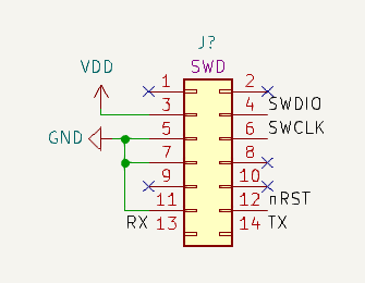
It’s really worth paying attention to the programming aspects of a board design. For STM32 and SAMD I would really recommend making space for this header:
it’s a 1.27mm pitch 2x7 male header, which doesn’t really take too much space. And if you put it on there like this, you can directly plug in your ST-Link (also the ST-Link Mini v3 with its supplied cable). You’ll get SWD programming and Serial debug output via the ST-Link, and you won’t have to mess with BOOT0 or Reset buttons.
For USB or any other kind of programming you generally need the BOOT0 and Reset buttons. With those it is easy to put the chip in boot-loader mode, and then you can easily program it using any of the standard methods, which for current STM32s even include I2C and CAN-bus. Certainly DFU via USB or Serial is supported.
Of course, all kinds of other schemes can be concocted to put the MCU in programming mode and program it. You can write your own boot-loaders if you have custom logic for the chip boot-up sequence. But generally speaking I would avoid doing that kind of stuff if possible, it will be quite some effort with little direct impact on the actual task of moving motors
Yeah well I needed the BOOT0 pin and the SWCLK. What can I say. Another possibility would be to just change the nBOOT0 bit value with the ST-link, so that it always jumps to dfu, unless its been flashed with “Run after programming”. That could work for debugging…
Edit: Good thing I broke out the NRST line on the ST-link adaptor. Choosing Hardware Reset in Cube_programmer, the SWD connection was established and the target is now resetting to dfu mode.
Awesome, from PlatformIO i can upload through USB and the program runs after the FLASH is completed. This is good enough for now…
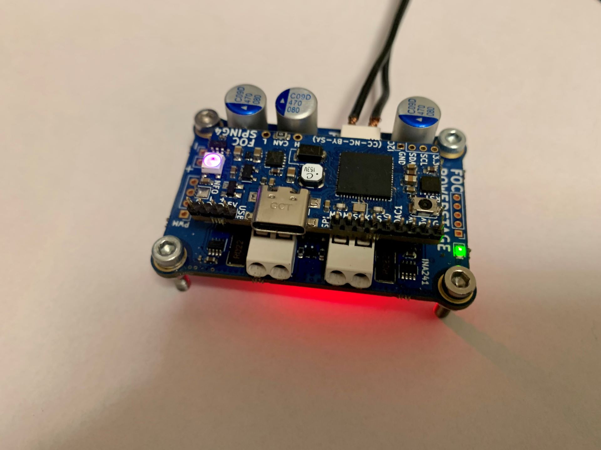
Ok, I think we are good to go, to perform the MT6835 test.
I was afraid I made some routing mistake, so I have postponed to attach the sensor. Im also waiting for magnets, so I cant test it before they arrive tomorrow or the day after.
The LED is attached to Pin 10 (PWM output) on the MT6835. Now its constantly on, but it can be set by writing to PWM_POL (Polarity), I think. I might use a larger value resistor, since its quite bright (Red). It was just intended for the calibration routine, if the SPI interface is not connected.
Edit: Im actually unsure if the PWM output can be turned of. If I move a magnet around the device, the LED flickers, so maybe it will just be representing the angle in brightness…
Hmm… was looking at my shipment, with the magnets, at UPS but because of some mixup he couldn’t hand it out. I can pick it up next Tuesday. Signing out till then.
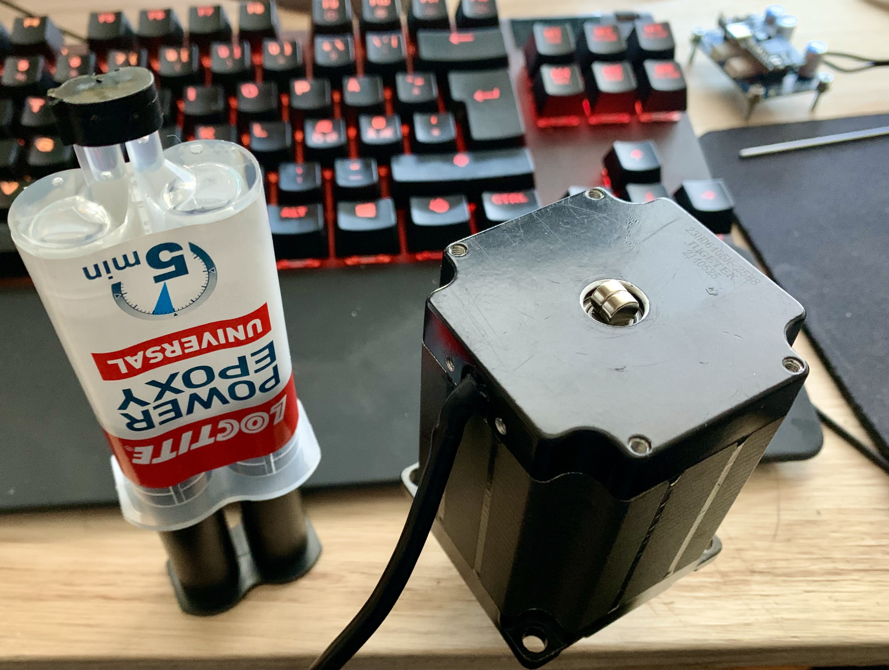
Yeah, I spoke with customs, plus the custom chieften, they wouldn’t let me open my own package. Anyways, I think I managed to center these two bad boys