Hey,
I’m having problems with the torque and voltage control.
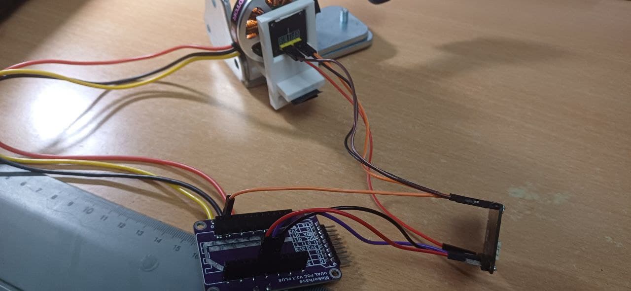
I am building a 2-DOF GImbal to align a camera.
I am using:
- GM5208-24 motors from iPower
- as5048a encoder
- Nucleo f446re
- SimpleFOC mini v1.0
- labor power supply
Yesterday I assembled my construction for the first time and had already successfully tested the individual motors and sensors in advance.
After the assembly I was able to control and align both motors but both motors showed the following behavior:
They approached the individual target angles but after a certain limit the motors block and simply start to draw more current. While this is happening, the motors do not react to further inputs.
To get to the bottom of the problem, I checked and tested the following things today:
- Wiring
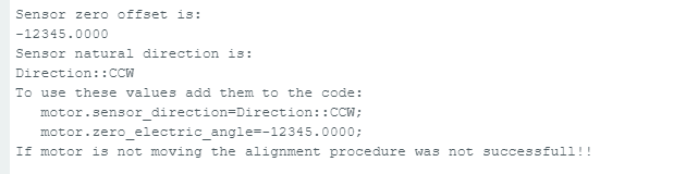
- Sensor values, both in the program and with the sensor test examples
- open-loop Velocity
- open-loop position
- closed loop velocity
- torque control
- Replacing the drivers
While my pitch axis now works in all modes (PINS were inserted incorrectly), I have problems with the yaw axis. Open-loop works fine in terms of speed and position. The closed-loop velocity does not work. I then tested the torque control to rule out controller problems and the motor now runs at 2V for about 27 revolutions and then stops. During the revolutions you can hear that a kind of friction occurs at two points of the rotation which slows down the motor (no mechanical friction, the motor can rotate freely if no voltage source is connected). If the target voltage is set to 0, the motor can be rotated without any noticeable force. If I set a voltage of 12v, then the motor holds its position after stopping but does not turn any further. I have already read most of the forum entries on similar topics and unfortunately have had no success in finding a solution so far. Has anyone had a similar problem?
Otherwise, many thanks to all those who have contributed to this project and made it possible for me to complete my project!
Thats the code i use for torque-control:
/**
- Torque control example using voltage control loop.
- Most of the low-end BLDC driver boards doesn’t have current measurement therefore SimpleFOC offers
- you a way to control motor torque by setting the voltage to the motor instead hte current.
- This makes the BLDC motor effectively a DC motor, and you can use it in a same way.
*/
#include <SimpleFOC.h>
// magnetic sensor instance - SPI
#define AS5048_CS_2_PIN PD2
SPIClass SPI_3(PC12, PC11, PC10);
// Sensor-Objekt
MagneticSensorSPI sensor = MagneticSensorSPI(AS5147_SPI, AS5048_CS_2_PIN);
// magnetic sensor instance - I2C
// MagneticSensorI2C sensor = MagneticSensorI2C(AS5600_I2C);
// magnetic sensor instance - analog output
// MagneticSensorAnalog sensor = MagneticSensorAnalog(A1, 14, 1020);
// BLDC motor & driver instance
BLDCMotor motor = BLDCMotor(11);
BLDCDriver3PWM driver = BLDCDriver3PWM(PC6, PC7, PC8, PC9);
// Stepper motor & driver instance
//StepperMotor motor = StepperMotor(50);
//StepperDriver4PWM driver = StepperDriver4PWM(9, 5, 10, 6, 8);
// voltage set point variable
float target_voltage = 2;
// instantiate the commander
Commander command = Commander(Serial);
void doTarget(char* cmd) { command.scalar(&target_voltage, cmd); }
void setup() {
// use monitoring with serial
Serial.begin(115200);
// enable more verbose output for debugging
// comment out if not needed
SimpleFOCDebug::enable(&Serial);
// initialise magnetic sensor hardware
SPI_3.begin();
sensor.init(&SPI_3);
// link the motor to the sensor
motor.linkSensor(&sensor);
// power supply voltage
driver.voltage_power_supply = 12;
driver.init();
motor.linkDriver(&driver);
// aligning voltage
motor.voltage_sensor_align = 5;
// choose FOC modulation (optional)
motor.foc_modulation = FOCModulationType::SpaceVectorPWM;
// set motion control loop to be used
motor.controller = MotionControlType::torque;
// comment out if not needed
motor.useMonitoring(Serial);
Greetings
Thomas
It is quite possible that the back EMF reached the PSU or MC via other pins.
– arch